MSP430FR6047: How can I use the MSP430FR6047 to obtain the correct ADC waveform for a sound path length of 1-5 meters?

Part Number: MSP430FR6047

Tool/software:

Dear Cash Hao11,

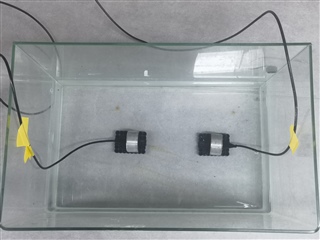
I have been researching whether the MSP430FR6047 chip can be used for open channel flow measurement in the range of 1-5 meters, as opposed to the pipe measurement provided in the official documentation. During a recent experiment, I observed some phenomena that I will describe below. In this experiment, the sound path distance was 0.8 meters, and the location was an indoor water tank.

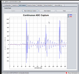
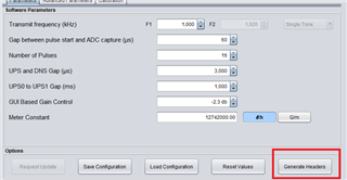
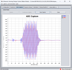
First, I completed the connection of the ultrasonic transducer and the development board (MSP430FR6047) following the steps in the official manual, and then I flashed the corresponding bin file. After setting the parameters on the USS GUI, I opened the ADC capture interface and saw a very strange waveform. The UPS waveform was almost a straight line (compared to the standard capture waveform provided in the official documentation).

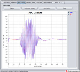
What's even stranger is that when I checked the wiring and reconnected, the waveform amplitude dropped directly to 20-30 (with all other USS parameters remaining unchanged).

I cannot understand the underlying reason for this and would appreciate your help in solving this mystery.

  • Hi,

    It could just be some reflection noise received on the DNS signal. 

    You can try to change USS_SEQUENCE_SELECTION to USS_CAPTURE_SEQUENCE_SELECTION_CH1_CH0. It will transmit the DNS signal first. In this case, you should find the DNS signal as a line according to my theory. 

    Best regards,

    Cash Hao

  • Hi,

    Okay, I understand your point. However, I couldn't find the parameter "USS_SEQUENCE_SELECTION" you mentioned in the USS GUI. Do I need to open the demo project, modify the parameters, and then compile and upload the code? Moreover, a more fundamental question is whether it is unreliable or even impossible to use the MSP430FR6047 for time-of-flight measurements in an open channel of 1-5 meters?

    Best regards,

    Tiger Cui

  • Do I need to open the demo project, modify the parameters, and then compile and upload the code?

    Yes. You need to do it. 

    We do not have much experience working with a meter with its diameter is from 1 to 5 meters. You can try with this application note, and check if it can be used in your application. 

    TIDA-01486 reference design | TI.com

    Best regards,

    Cash Hao

  • Hi,

    I have set up a new experimental environment. In the new experiment, the distance between the ultrasonic transducers is 15 cm. I then connected the MSP430FR6047 and opened the USS utility. I captured the following three images. In the first image, the ADC waveform has been adjusted to meet the requirements of the official documentation. The second image shows the waveform window, which seems a bit odd. Could the variance of delta TOF be too large? Please help me identify the issue. The third image displays the reported error codes. I don't quite understand the meaning of error code 135. Could you please clarify this for me?

    waveformERROR CODE

    Best regards,

    Tiger Cui.

  • Hi,

    For the error code 135, you can set the USS_ALG_MAX_SAMPLE_SHIFT a larger number in the code like 80/100/120 to avoid this error. 

    The waveform page looks abnormal to me. The dTOF result varies a lot in that figure. What test condition do you get this result?

    Best regards,

    Cash Hao

  • Hi,

    I know how to avoid the error code now. So, my ADC sampling result image should be fine, right? Below is the scene of my experiment.Could it be because there are many small holes in the cushion at the bottom of the transducer?

    Best regarads,

    Tiger Cui

  • Hi,

    I would not say your ADC capture is all good for me. There is a DC offset around 150 ADC codes on the ADC capture data. It usually caused by a higher PGA gain settings. But I do not see your configuration, I am not sure where this offset come from. 

    And you directly put your transducer into the water. I am not sure if this is okay. Usually, the transducer is not water proofed. It can not work in the water. 

    Best regards,

    Cash Hao

  • Hi,

    Yes, you are right. I increased the 'GUI Based Gain Control' parameter in the utility. If I use the default value, my ADC amplitude is only around 80.

    Best regards,

    Tiger Cui

  • Hi,

    The fastest ADC speed of the MSP430FR6047 is 8M sps (samples per second). However, its datasheet mentions that the high-precision time measurement resolution is less than 5ps (picoseconds). With a maximum sampling rate of 8M sps, the interval between samples is 125 picoseconds, so the sampling time resolution should be 125ps, not 5ps. Am I misunderstanding something, or is there an error in the datasheet? If what the manual says is true, how is this achieved? Is it through interpolation of the sampled ADC waveform data? The recommended ADC sampling frequency for a 1MHz probe is 3.6MHz, which corresponds to a time measurement resolution that is far from 5ps. It's hard to imagine this being achieved solely through interpolation; is there additional hardware assistance? I look forward to your response.

    Best regards,

    Tiger Cui

  • Hi,

    The 5ps is improved by interpolation method on the cross correlation data. 

    I think you understand mandarin, please check this video b23.tv/iQREde1

    Best regards,

    Cash Hao

  • Hi,

    Thank you very much for your response. After watching the video and consulting the official documentation, I conducted a simulation in MATLAB. I will upload the MATLAB code as an attachment. In the simulation, the sampling frequency of the ADC is 3.6MHz, the signal frequency is 1MHz, and the duration is set to 60 microseconds. Under these conditions, after performing cosine interpolation on the cross-correlation results, the accuracy can only reach 275ns, which is still a significant gap from 5ps. Could you please explain why this is the case? Did I make any mistakes in my simulation code? I would greatly appreciate your clarification.

    Best regards,

    Tiger Cui

    % MATLAB代码,生成两个离散信号序列,其中一个信号相较于另一个信号延迟200纳秒
    
    % 参数
    fs = 3.6e6; % 采样率,单位为赫兹
    f_signal = 1e6; % 信号频率,单位为赫兹
    delay = 200e-9; % 延迟时间,单位为秒
    duration = 60e-6; % 持续时间,单位为秒
    
    % 时间向量
    t = 0:1/fs:duration; % 时间向量,持续时间由duration决定
    
    % 生成原始信号
    signal1 = sin(2 * pi * f_signal * t);
    
    % 延迟样本数量
    delay_samples = round(delay * fs);
    
    % 生成延迟信号
    signal2 = [zeros(1, delay_samples), sin(2 * pi * f_signal * t(1:end-delay_samples))];
    
    % 绘制两个信号在同一张图中
    figure;
    plot(signal1, 'b'); % 原始信号用蓝色表示
    hold on;
    plot(signal2, 'r'); % 延迟信号用红色表示
    title('原始信号和延迟信号');
    xlabel('采样点的索引');
    ylabel('振幅');
    legend('原始信号', '延迟信号');
    grid on;
    hold off;
    
    % 提取20-40点范围内的信号
    signal1_segment = signal1(20:40);
    signal2_segment = signal2(20:40);
    
    % 计算互相关
    [cross_corr, lags] = xcorr(signal1_segment, signal2_segment);
    
    % 找到互相关的峰值索引
    [~, max_index] = max(cross_corr);
    
    % 余弦插值计算更精确的峰值点位置
    alpha = cross_corr(max_index - 1);
    beta = cross_corr(max_index);
    gamma = cross_corr(max_index + 1);
    
    omega = acos((alpha + gamma) / (2 * beta));
    phi = atan((alpha - gamma) / (2 * beta * sin(omega)));
    delta = -phi / omega;
    
    % 计算更精确的峰值点位置
    peak_lag_interp = lags(max_index) + delta;
    
    % 显示结果
    disp(['峰值索引: ', num2str(lags(max_index))]);
    disp(['插值后的峰值索引: ', num2str(peak_lag_interp)]);
    
    % 计算dTOF
    dTOF = -(lags(max_index) + delta) / fs;
    disp(['dTOF: ', num2str(dTOF), ' 秒']);
    

  • Hi,

    Your code looks correct from my side. However, I think this test code can only prove the accuracy of this method, not the resolution of the cosine interpolation method. And about the resolution of cosine interpolation in MCU, I think it is related to how they define the data format. I do not know how to calculate this resolution in formula. However, based on the dTOF result in water meter application. At zero flow, the STD of dTOF is usually around 30ps. So, the resolution of the dTOF result should also has the same scale or even smaller of its result.

    Best regards,

    Cash Hao

  • Hi,

    I am currently facing some tricky issues. After making some modifications to the USS_WATER_Demo project (including adding my designed algorithm), I want to observe the changes in algorithm parameters and the final output in debug mode. Therefore, I need to set breakpoints. The problem is that, in this case, I cannot connect to the USS GUI, and thus cannot transfer the basic parameters into the program. Is there a version of USS_WATER_Demo that allows manual modification of main parameters without using the GUI, or is there a way to observe the variable window (in Debug mode) while using the GUI?

    Best regards,

    Hu Cui

  • Hi,

    You can use generate headers functions of the USS GUI. Then replace the header files in your project. Then after you build and download your project. You do not need to update parameters through USS GUI again. 

    And in debug mode, it usually can not use GUI at the same time. 

    Best regards,

    Cash Hao

  • Hi,

    Thank you for your response. I achieved the parameter passing of the USS GUI and observed the variable values by disabling the LPM mode. Your suggestion would also be a better solution. I now want to use IIC to transmit the waveform data collected by the ADC. Could you please let me know if you have any example code or demonstration code for using IIC to transmit data externally with the MSP430FR6047?

    Best regards,

    Hu Cui

  • Hi,

    You want to develop your own GUI instead of using USS GUI? 

    There are some code examples you can refer to in the below link.

    https://dev.ti.com/tirex/explore/node?node=A__ABziZFVjgbNp8cm.JAo1jQ__msp430ware__IOGqZri__LATEST

    Best regards,

    Cash Hao

  • Hi,

    Thank you for your response.

    During debugging, I encountered several issues, and I would appreciate your help in looking into them. The first issue is under what circumstances the defined variable would be stored in Register R7. In the debugging image I uploaded below, the variable index_x is stored in Register R7, and from line 710 to line 719, its value changes significantly, which is clearly not expected.

    The second issue is that during debugging, the defined variable delta prompts "identifier not found". I defined this variable in the function and initialized it before assigning a value to it. Why does this prompt occur? Could it be that the compiler optimized this variable out due to the optimization level?

    Best regards,

    Hu Cui

  • Hi,

    It could related to the optimization level. Or the way you calculate the results. You can try with below method and check if it works on your side.

    double alpha=0.0,beta=0.0,delta=0.0, omega=0.0,psi=0.0;

    sum1 = xx[index_x - 1];
    sum2 = xx[index_x ];
    sum3 = xx[index_x + 1];
    omega = (double)(sum1+sum3)/(double)(2*sum2);
    alpha=acos(omega);
    psi=(double)(sum1-sum3)/(double)(2*sum2*sin(alpha));
    beta=atan(psi);
    delta=-beta/alpha;

    Best regards,

    Cash Hao

  • Hi,

    Through single-step debugging, I finally identified the problem. The issue lies in the use of trigonometric functions. Using functions like sin(), acos(), atan() didn't yield the correct values. Ultimately, I resolved the issue by using sinl(), acosl(), atanl(). However, during debugging, I discovered a few new problems. The first issue is as follows, as seen in the first image: in the variables window, the value of xx[index_x] is 32733, but the value of 2*xx[index_x] is -70. The array xx is of int type. Why does this happen? The second issue, please refer to the last four images. The images were captured during step-by-step debugging by setting breakpoints in adjacent code. It can be observed that the variable's lifecycle is very short. Even though the variables are within the same function and adjacent code, why do the values change so quickly? (As seen in the fourth and fifth images of 'calc'). These are my two questions, and I kindly request your assistance in resolving them.

    Best regards,

    Hu Cui.

  • Hi,

    1. The correlation result value should be saved in a int32 format. In your code, it seems that you are using int16 format. With int32 format, you should avoid your issue.

    And you are using sinl() instead of sin(). In the math.h file you will need to input long double format data into sinl() function. You data is not long double format. I do not think it is correct to call sinl() function.

    2. It seems after your code line 733, the calc is not used after line. So, the area is optimized to save other data. 

    Best regards,

    Cash Hao

  • Hi,

    Thanks for your reply. I have some new problems.

    Yesterday, I was able to obtain correct ADC waveforms with a 1m signal path length, but today, no matter what I do, I cannot get a normal ADC waveform. I checked the wiring and abandoned using my modified compiled program, instead using the official MSP430FR6047EVM_USS_Water_Demo_LPM_02_40_00_00.txt firmware. Even so, I still cannot reproduce the ADC waveform I obtained yesterday. After programming the modified program into the board, updating parameters always reports an error: "The output frequency of the HSPLL is invalid." Sometimes this error will disappear after a while and switch to another error; other times, the error persists.

    I used a network analyzer to check the transducers, and they are not problematic. To verify the reception of the FR6047 development board, I injected a signal using a signal generator and observed the signal with the GUI, and there were no issues.

    I am eager to understand where the problem lies. Could you please help clarify this for me?

    Best regards,

    Hu Cui.

  • Hi,

    You can try set the USS_DIAGNOSTIC_MODE to USS_diagnostics_mode_0. It could block most of the checking HSPLL frequency valid function. 

    Best regards,

    Cash Hao

**Attention** This is a public forum