This thread has been locked.

If you have a related question, please click the "Ask a related question" button in the top right corner. The newly created question will be automatically linked to this question.

MSP430F6779A: Question for using two 4148 Diode at AFE current side

Part Number: MSP430F6779A
Other Parts Discussed in Thread: TIDM-3PHMTR-TAMP-ESD, MSP430F6779

Tool/software:

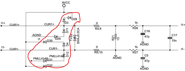
According to refrence circuit diagram of TIDM-3PHMTR-TAMP-ESD,  two 4148 diode were used at each AVCC and AGND line (I+, I-)

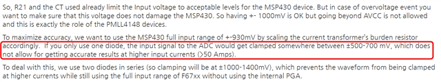
I found that someone also asked same question and TI engineer replied like below. (Refer to red squre mark)

(llink : https://e2e.ti.com/support/microcontrollers/msp-low-power-microcontrollers-group/msp430/f/msp-low-power-microcontroller-forum/1189101/tidm-3phmtr-tamp-esd-msp430f67791aipeu?tisearch=e2e-sitesearch&keymatch=MSP430F6%252A%2520diode)

This is my question.

1. if input current is less than 50A, is it OK if I use just one 4148 diode? (we use 32A)

2. we use shunt resistor for current sensing and sensing voltage is approximately 10mV. we will use intenal PGA amp gain=64.

    Should we also use two 4148 diode in this case??

  • Please let me involve SEM team for the TI design question.

  • How can I involve you? Is there any procedure?

  • Hello Sangho,

    see my answers below:

    1. if input current is less than 50A, is it OK if I use just one 4148 diode? (we use 32A)

    The Input current only is relevant as long as the max. Voltage across the SHUNT (e.g. 50A x 200 uOhm = 10mV ) you use is compliant with the ADC specification. This is just an example, assuming you have a 200 uOhm SHUNT.

    2. we use shunt resistor for current sensing and sensing voltage is approximately 10mV. we will use internal PGA amp gain=64.

        Should we also use two 4148 diode in this case??

    I think you can use a single diode in your case but that has to be tested (TI has not tested that). I'd suggest to test with a higher current (e.g. 40A instead of 32A) to ensure you have sufficient margin for the measurement and check the behavior across temperature and supply voltage range.

    Regards,

    Milen

  • Dear Milen 

    Thanks for your reply.

    We are also considering use 80A input current. (designing both 32A and 80A )

    Regardless of the input current value, if input voltage across the SHUNT is between 10mV~18mV, it doesn't matter one clamping diode? Because ADC input voltage range is less than 930mV.

    Am I right to understand?

    Reference circuit diagram with CT has Burden resistor. But in my case, I use Shunt Resistor for current sensing, so there is no Burden Resistor.

    the difference of current sensing method is also relevant? 

    I found another reply like below.

    Link 1

    2. If question 1 is true, why then are there two diodes placed in series? The diodes used in the design are PMLL4148 which has a maximum forward voltage of 1V. By placing two diodes in series, the voltage drop towards a supply rail is 2V. The circuit will therefore clip at +5.3V or -2V, which is way beyond the withstand limit of the SD24 input specification. Why are two diodes used in series and not just one?

    Assuming that your max negative input reaches -930mV when your RMS current through the CT is 100A, a single diode with a max forward voltage of 1V would most likely start conducting under normal operating conditions, which is not ideal. This would explain why two diodes were used in series to increase the limit to 2V. Thankfully, the MSP430F6779 has ESD diodes that offer a small amount of protection to low, secondary over-voltage conditions.

    Link 2

    The diodes are for clamping the analog input pins so that they are within the absolute voltage range of these pins.  Instead of the 1-diode arrangement shown in your last post, it would be better to use the 2-diode implementation you showed in your post from May 27th.  The 2-diode implementation has a higher clamping voltage, which would prevent premature voltage clamping at higher currents.

**Attention** This is a public forum