This thread has been locked.

If you have a related question, please click the "Ask a related question" button in the top right corner. The newly created question will be automatically linked to this question.

MSP430F249: UART RX is not working

Part Number: MSP430F249

Tool/software:

Hi,

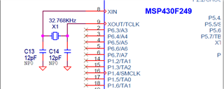
I am using the example code to enable UART msp430x24x_uscia1_uart_05_9600.c for MSP430F249

The example codes works fine when I run the code through IAR.

I can see the output with the character I enter in the Teraterm port (9600 baudrate). 

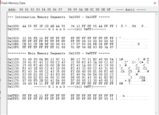
When I use the HEX Image and flash using FETPro Tool, Its not working. I mean the RX input is echoed to TX.

Please help to identify the issue.

  • Can you share your code?

  • //******************************************************************************
    // MSP430x24x Demo - USCI_A1, Ultra-Low Pwr UART 9600 Echo ISR, 32kHz ACLK
    //
    // Description: Echo a received character, RX ISR used. Normal mode is LPM3,
    // USCI_A1 RX interrupt triggers TX Echo.
    // ACLK = BRCLK = LFXT1 = 32768Hz, MCLK = SMCLK = DCO ~1.045Mhz
    // Baud rate divider with 32768Hz XTAL @9600 = 32768Hz/9600 = 3.41
    // => UCBRx = 0x03; In UCA1MCTL: UCBRSx = round(0.41*8) = 0x03
    // //* An external watch crystal is required on XIN XOUT for ACLK *//
    //
    // MSP430F249
    // -----------------
    // /|\| XIN|-
    // | | | 32kHz
    // --|RST XOUT|-
    // | |
    // | P3.6/UCA1TXD|------------>
    // | | 9600 - 8N1
    // | P3.7/UCA1RXD|<------------
    //
    // B. Nisarga
    // Texas Instruments Inc.
    // September 2007
    // Built with CCE Version: 3.2.0 and IAR Embedded Workbench Version: 3.42A
    //******************************************************************************
    #include <msp430.h>

    int main(void)
    {
    WDTCTL = WDTPW + WDTHOLD; // Stop WDT
    P1DIR = 0xFF; // All P1.x outputs
    P1OUT = 0; // All P1.x reset
    P2DIR = 0xFF; // All P2.x outputs
    P2OUT = 0; // All P2.x reset
    P3SEL = 0x0C0; // P3.6,7 = USCI_A1 TXD/RXD
    P3DIR = 0xFF; // All P3.x outputs
    P3OUT = 0; // All P3.x reset
    P4DIR = 0xFF; // All P4.x outputs
    P4OUT = 0; // All P4.x reset
    P5DIR = 0xFF; // All P5.x outputs
    P5OUT = 0; // All P5.x reset
    P6DIR = 0xFF; // All P6.x outputs
    P6OUT = 0; // All P6.x reset

    UCA1CTL1 |= UCSSEL_1; // CLK = ACLK
    UCA1BR0 = 0x03; // 32kHz/9600 = 3.41
    UCA1BR1 = 0x00; //
    UCA1MCTL = UCBRS1 + UCBRS0; // Modulation UCBRSx = 3
    UCA1CTL1 &= ~UCSWRST; // **Initialize USCI state machine**
    UC1IE |= UCA1RXIE; // Enable USCI_A1 RX interrupt

    __bis_SR_register(LPM3_bits + GIE); // Enter LPM3, interrupts enabled
    }

    // Echo back RXed character, confirm TX buffer is ready first
    #if defined(__TI_COMPILER_VERSION__) || defined(__IAR_SYSTEMS_ICC__)
    #pragma vector=USCIAB1RX_VECTOR
    __interrupt void USCI1RX_ISR(void)
    #elif defined(__GNUC__)
    void __attribute__ ((interrupt(USCIAB1RX_VECTOR))) USCI1RX_ISR (void)
    #else
    #error Compiler not supported!
    #endif
    {
    while (!(UC1IFG&UCA1TXIFG)); // USCI_A1 TX buffer ready?
    UCA1TXBUF = UCA1RXBUF; // TX -> RXed character
    }

  • Have you reset (or power-cycled) the board since you programmed it? As I recall, the FET-Pro software leaves the device in Reset unless you check a box somewhere.

  • Hi Swarna,

    Maybe you can check the difference betwwen the one compiled by IAR, and the one you read out from FET tool.

    If it is the same, I suspect whether you have let the device enter some mode which are not running the application code. For eaxmple, reset mode, or bsl mode.

    B.R.

    Sal

  • Hi,

    The hex there is no change. 

    I haven't done any crystal settings. Is this the reason the application is not getting any clk? 

    Can you please share the code to configure. I tried with some examples but not successful. 

  • Hi Swarna,

    The hex there is no change. 

    So, is it normal when you use IAR debug mode and then exit debug mode and reset the device?

    I haven't done any crystal settings. Is this the reason the application is not getting any clk? 

    The example you share has configured the CLK. 

    Maybe you can use internal clock rather than the ACLK for the uart, the reference code is below:

    https://dev.ti.com/tirex/explore/node?node=A__AKlljD0-u6GH-hOGGBHFtg__msp430ware__IOGqZri__LATEST 

    B.R.

    Sal

**Attention** This is a public forum