This thread has been locked.

If you have a related question, please click the "Ask a related question" button in the top right corner. The newly created question will be automatically linked to this question.

MSP430FR2433: UCBBUSY set while communicating with two sensors through I2C

Part Number: MSP430FR2433

Tool/software:

Hello everyone!

I'm interfacing MPU-6050 accelerometer and CCS811 gases sensor through I2C.

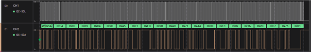
Using a logic analyzer, it was chacked that after some time the UCBBUSY is set and a START bit is pending. Executing twice it hanged after requesting the data register of the gas sensor.

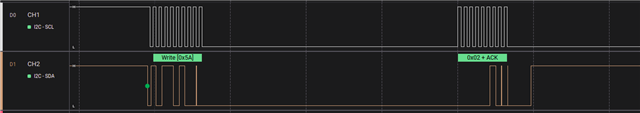
I think is worth note that scl line passes to high level later.

The code for write to/read from register is shown below:

// Wake up the MPU-6050
slaveAddress = MPU_ADDR;
TX_Data[1] = PWR_MGMT_1;
TX_Data[0] = 0x08;      // Set 8 MHz clock; disable temperature sensor
TX_ByteCtr = 2;
i2c_wr(slaveAddress);
__delay_cycles(50000); // According to datasheet, hold ~30 ms
                       // Because of gyroscope based clock oscillator
slaveAddress = CCS811_ADDR;         // Make transition from boot to application mode
TX_Data[0] = CCS811_APP_START;
TX_ByteCtr = 1;
i2c_wr(slaveAddress);
__delay_cycles(30000);

slaveAddress = CCS811_ADDR;
TX_Data[1] = CCS811_MEAS_MODE;
TX_Data[0] = 0x10;                  // Put CCS to normal mode, no interrupt enable
TX_ByteCtr = 2;
i2c_wr(slaveAddress);
__delay_cycles(15000);

while(1)
{
    // Register pointing
    slaveAddress = MPU_ADDR;
    TX_Data[0] = ACCEL_XOUT_H;          // First address of the set
    TX_ByteCtr = 1;
    i2c_wr(slaveAddress);

    // Read six bytes of data
    slaveAddress = MPU_ADDR;
    RX_ByteCtr = 6;
    i2c_rd(slaveAddress);

    xAccel  = RX_Data[5] << 8 | RX_Data[4];
    yAccel  = RX_Data[3] << 8 | RX_Data[2];
    zAccel  = RX_Data[1] << 8 | RX_Data[0];
    //--------------------------------------------------------------------------------//
    __delay_cycles(50000);
    //--------------------------------------------------------------------------------//
    slaveAddress = CCS811_ADDR;
    TX_Data[0] = CCS811_ALG_RESULT_DATA;
    TX_ByteCtr = 1;
    i2c_wr(slaveAddress);
    // Reading operation of environment data register
    slaveAddress = CCS811_ADDR;
    RX_ByteCtr = 8;
    i2c_rd(slaveAddress);

    co2Lvl = (RX_Data[0] << 8 | RX_Data[1]);
    tvocLvl = (RX_Data[2] << 8 | RX_Data[3]);

    __delay_cycles(100000);
} //End while

The register addresses are extracted from the respective device datasheets.

For reference, the I2C related code is here:

/**
 * Configuration of I2C module
 */
void i2c_conf(void)
{
    // I2C pins configuration
    P1SEL0 |= BIT2 | BIT3;

    // Disable the GPIO power-on default high-impedance mode to activate
    // previously configured port settings
    PM5CTL0 &= ~LOCKLPM5;

    // Configure USCI_B0 for I2C mode
    UCB0CTL1 |= UCSWRST;                    // Software reset enabled
    UCB0CTLW0 |= UCMODE_3 | UCMST;          // I2C mode, Master mode, SMCLK
    UCB0CTLW0 |= UCSSEL__SMCLK | UCSYNC;    // Use SMCLK as clock source, sync
    UCB0CTLW1 |= UCASTP_2;                  // Automatic stop generated by
                                            // reaching data acquisition boundary
    UCB0BR0 = 0x0008;                       // baudrate = SMCLK / 8 = ~100 kHz
    UCB0CTL1 &= ~UCSWRST;                   // Disable SW reset
}
/**
 * Write function
 */
void i2c_wr(unsigned char addr)
{
    while(UCB0CTL1 & UCTXSTP);          // Ensure stop condition sent

    UCB0CTL1 |= UCSWRST;
    UCB0I2CSA = addr;                   // Slave address
    UCB0TBCNT = TX_ByteCtr;
    UCB0CTL1 &= ~UCSWRST;
    UCB0IE |= UCTXIE | UCRXIE | UCBCNTIE;    // Enable Tx, RX and
                                             // byte count interruptions
    UCB0CTL1 |= UCTR;        // Transmitter mode
    UCB0CTL1 |= UCTXSTT;     // and send START condition

    __bis_SR_register(LPM0_bits|GIE);   // Enter LPM0 w/ interrupt
}
/**
 * Read function
 */
void i2c_rd(unsigned char addr)
{
    while(UCB0CTL1 & UCTXSTP);          // Ensure stop condition sent

    UCB0CTL1 |= UCSWRST;
    UCB0I2CSA = addr;                   // Slave address
    UCB0TBCNT = RX_ByteCtr;
    UCB0CTL1 &= ~UCSWRST;
    UCB0IE |= UCTXIE | UCRXIE | UCBCNTIE;              // Enable Tx and RX interruptions

    UCB0CTL1 &= ~UCTR;                  // Receiver mode
    UCB0CTL1 |= UCTXSTT;               // and send START condition

    __bis_SR_register(LPM0_bits|GIE);   // Enter LPM0 w/ interrupt
}
/**
 * UCB0 ISR
 */
#if defined(__TI_COMPILER_VERSION__) || defined(__IAR_SYSTEMS_ICC__)
#pragma vector = USCI_B0_VECTOR
__interrupt void USCIB0_ISR(void)
#elif defined(__GNUC__)
void __attribute__ ((interrupt(USCI_B0_VECTOR))) USCIB0_ISR (void)
#else
#error Compiler not supported!
#endif
{
  switch(__even_in_range(UCB0IV, USCI_I2C_UCBIT9IFG))
  {
    case USCI_I2C_UCRXIFG0:
            if (RX_ByteCtr--)
            {
                RX_Data[RX_ByteCtr] = UCB0RXBUF;  // Get received byte
            }
            break;
    case USCI_I2C_UCTXIFG0:
            if (TX_ByteCtr--)               // TRUE if more bytes remain
            {
                UCB0TXBUF = TX_Data[TX_ByteCtr];  // Load TX buffer
            }
        break;
    case USCI_I2C_UCBCNTIFG:
        __bic_SR_register_on_exit(CPUOFF);  // Exit LPM0
        break;
  }
}

Any help is appreciated.

  • Can you tell which transaction is failing? (Is it always the same one?)

  • Hello!

    I tested two more times, and yes, it is in the same transaction (request to read from CCS811_ALG_RESULT_DATA - the register that stores CO2 and TVOC data); it displaying the same condition too: UCBBUSY set and START bit pending.

    I also checked that some times the referred register have no data, so I wonder if the configuration or the circuitry is the main cause.

  • I'm guessing it's the CCS811 that's stretching the clock -- while it is possible for your code to inadvertently hang the bus, those accidents usually show up in the first few transactions. (Stretching the clock for a "long time" is called "hanging the bus", i.e. it's the same phenomenon on the bus). Neither the datasheet nor AN000369 mention clock stretching, but 5-minutes-with-Google tells me that the CCS811 does it under some circumstances.

    I wonder if the sensor is stretching the clock waiting for new data; I have seen this done in another sensor somewhere. There's nothing in the datasheet (nor App Note) that says you can't read register 0x02 if there's no new data -- they even include a copy of the STATUS register so you can read-then-check -- but every example I found only reads register 0x02 if DATA_READY=1. Since you've requested one reading per second, a quick experiment would be to extend your loop (delay at the bottom) from 100ms to 1000ms. Slightly more elaborate: enable then probe the nINT pin along with the bus.

    Are you using a commercial breakout board? I notice that the Adafruit board ties nWAKE low, but I don't know about others. You don't want it to float in any case.

  • One thing that I don't like to do with I2C code is allow for an infinite wait. Whenever I have something like "while(UCB0CTL1 & UCTXSTP);" I include a timeout. For debugging purposes I also tend to return a unique code for each error as that makes locating trouble easier.

    If the problem is a hanging start condition at the beginning of the read, I would first check to see that the previous write (where you set the register number to read) finished correctly. Also, the usual way to do this is as a single transaction with a repeated start.

  • I added a verification code (accessing CCS811_STATUS) before check the data register (CCS811_ALG_RESULT_DATA) and the error persists.

    I'll take a look at this. 

    About the nWAKE pin, it needs to be grounded. Strangely, I was getting NACKs when reading the CCS address; it came back to work letting RST and INT unconnected. 

  • I recoded the ISR to implement the repeated START:

    #if defined(__TI_COMPILER_VERSION__) || defined(__IAR_SYSTEMS_ICC__)
    #pragma vector = USCI_B0_VECTOR
    __interrupt void USCIB0_ISR(void)
    #elif defined(__GNUC__)
    void __attribute__ ((interrupt(USCI_B0_VECTOR))) USCIB0_ISR (void)
    #else
    #error Compiler not supported!
    #endif
    {
      switch(__even_in_range(UCB0IV, USCI_I2C_UCBIT9IFG))
      {
        case USCI_I2C_UCRXIFG0:
                if(RX_ByteCtr)
                {
                    RX_Data[RX_ByteCtr--] = UCB0RXBUF;  // Get received byte
                    UCB0IFG |= UCRXIFG0;
                }
                else
                {
                    UCB0CTLW0 |= UCTXSTP;
                    UCB0IFG &= ~UCRXIFG0;
                    __bic_SR_register_on_exit(CPUOFF);      // Exit LPM0
                }
            break;
        case USCI_I2C_UCTXIFG0:
                    if(TX_ByteCtr)
                    {
                        TX_Data[TX_ByteCtr--] = UCB0TXBUF;  // Get received byte
                        UCB0IFG |= UCTXIFG0;
                    }
                    else
                    {
                        UCB0CTLW0 |= UCTXSTP;
                        UCB0IFG &= ~UCTXIFG0;
                        __bic_SR_register_on_exit(CPUOFF);      // Exit LPM0
                    }
            break;
      }
    }

    It's worse, because I cannot make a communication, dropping SCL and SDA in the first I2C comm attempt (setting MPU).

  • Usually you write something to TXBUF in response to a transmit interrupt.

    The receive interrupt does redundant and strange things. Redundant because UCRXIFG0 is cleared by reading UCB0IV and UCB0RXBUF so there is no need it clear it explicitly.

    Strange in that there is an easier way to deal with the stop condition when reading data. When the ISR begins, the I2C hardware is waiting and one of two things can happen. You can read RXBUF and it will begin receiving the next byte. Or you can set TXSTP and it will generate a stop. As written, it receives an extra byte that it just ignores.

  • In the TX part I made a huge mistake, too stressed.

    That's the new version:

    #if defined(__TI_COMPILER_VERSION__) || defined(__IAR_SYSTEMS_ICC__)
    #pragma vector = USCI_B0_VECTOR
    __interrupt void USCIB0_ISR(void)
    #elif defined(__GNUC__)
    void __attribute__ ((interrupt(USCI_B0_VECTOR))) USCIB0_ISR (void)
    #else
    #error Compiler not supported!
    #endif
    {
      switch(__even_in_range(UCB0IV, USCI_I2C_UCBIT9IFG))
      {
          case USCI_I2C_UCRXIFG0:
              RX_Data[--RX_ByteCtr] = UCB0RXBUF;  // Get received byte
              if(!RX_ByteCtr)
              {
                  if(restart)
                  {
                      UCB0CTL1 |= UCTXSTT;
                      while(UCB0CTL1 & UCTXSTT);          // Ensure START sent
    
                      restart = 0;
                  }
                  else
                  {
                      UCB0CTL1 |= UCTXSTP;
                      while(UCB0CTL1 & UCTXSTP);          // Ensure STOP sent
                  }
                  __bic_SR_register_on_exit(CPUOFF);  // Exit LPM0
              }
              break;
          case USCI_I2C_UCTXIFG0:
              UCB0TXBUF = TX_Data[--TX_ByteCtr];  // Passes byte to transmit buffer
              if(!TX_ByteCtr)
              {
                  if(restart)
                  {
                      UCB0CTL1 |= UCTXSTT;
                      while(UCB0CTL1 & UCTXSTT);          // Ensure START sent
    
                      restart = 0;
                  }
                  else
                  {
                      UCB0CTL1 |= UCTXSTP;
                      while(UCB0CTL1 & UCTXSTP);          // Ensure STOP sent
                  }
                  __bic_SR_register_on_exit(CPUOFF);  // Exit LPM0
              }
              break;
      }
    }

    The hanging bus issue was resolved! Now the other problem is that its readings are wrong.

    Seems like the counter is being messed up.

    In the following block of code, 3 writes should be performed.

    slaveAddress = CCS811_ADDR;         // Make transition from boot to application mode
    TX_Data[0] = CCS811_APP_START;
    TX_ByteCtr = 1;
    restart = 1;
    i2c_wr(slaveAddress);
    __delay_cycles(22000);
    TX_Data[1] = CCS811_MEAS_MODE;
    TX_Data[0] = 0x10;                  // Put CCS to normal mode, no interrupt enable
    TX_ByteCtr = 2;
    i2c_wr(slaveAddress);

    But this is being done:

  • So much wrong I don't think I can cover it all.

    First, when doing a restart, you have to switch the I2C port from write to read. (Clear UCTR) Otherwise it sends the device address with the write bit set. Again.

    Example:

      IFG2 &= ~UCB0RXIFG;         // make sure no previous interrupt
      UCB0CTL1 &= ~UCTR;          // restart as receiver
    
      UCB0CTL1 |= UCTXSTT;        // I2C repeated start condition
      IE2 |= UCB0RXIE;                // enable receive interrupt
    

    (For a G series part so details are different.)

    Not sure why the receive code checks the restart flag. You never start a receive and switch to transmit.

    That command sending APP_START seems wrong. You usually have to send a register address/ value pair. But looking at the device data sheet, that seems correct. Sort of. Have you loaded an application? Did you read the status register to check that as recommended? Why did you set the restart flag? That will cause no end of trouble. (Think about what value your byte counter will have on the next transmit interrupt.)

  • Hello!

    Well, I had many issues with the TX interrupt, triggering in wrong time (before enter low power mode) and not triggering when it should; this caused some bytes to be read more than expected.

    I switched back to using automatic STOP, and now the communication seems more stable. So I'll keep it this way for a while.

    Regarding APP_START, you're right, it's not ecessary. When I first coded the gas sensor interface, I thought it was necessary to boot it up.

**Attention** This is a public forum