


Other Parts Discussed in Thread: LMP91000, MSP430FR2355, LM358
Tool/software:
I asked a question a little bit back where I get a clean signal out of the LMP91000, but when I implement my potentiostat using the SACs on the MSP430FR2355 chip I get a lot of low frequency non-sinusoidal noise (<1Hz noise). We did some testing with a separate opamp and got good results so we implemented that circuit in place of the SAC opamps. We still wanted the ability to set the bias dynamically, so I left the DACs in place and output 2 of them via a unity gain amplifier from the SAC. Both DACs have the exact same level set to them throughout my testing (~0.45V).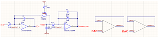
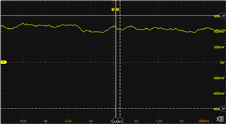
This is a scope capture at the "ECHEM_VOUT" node as implemented in the schematic above. All of that low frequency noise (+/-100mV or so) is not supposed to be there.
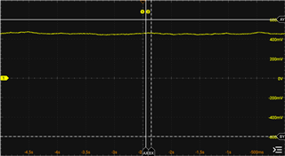
After hours of troubleshooting with hardware changes and firmware changes I was able to get the most improvement in my signal by applying the same DAC output to the non-inverting inputs of both U3 opamp channels (ie. OPA0OUT goes to both U3Pin3 and U3Pin5). Low frequency noise closes to +/-20mV.
The evidence is telling me that the DAC outputs from different SAC modules are not balanced, and when they get imbalanced that gets amplified by my gain and is causing the chaotic low frequency signals I've been tracking for a bit now.
So my question: What can I do, if anything, to help the DACs stay balanced?
If that's not possible then TI really needs to have some application note around this issue as it will be prevalent in ANY electrochemical gas sensor potentiostat circuit using the SAC peripheral, and force you to be willing to accept a 3% noise error in your sensor output, or give up the convenience of the DACs all together.
Things I've tried:
1) Put a low pass filter (1k Ohm with 0.1uF) between OPA0OUT and U3Pin3, and also between OPA3OUT and U3Pin5. No improvement in noise.
2) Added a ferrite bead inductor (10uH) in front of the low pass filter from 1 above. No improvement in noise.
3) Added a capacitor (10uF) from OPA0OUT to OPA3OUT in the hopes this would be enough to couple them together assuming there was some high/low frequency noise on one or both of them which was throwing them out of balance. No improvement in noise was seen.
4) A bunch of other stuff which didn't target the DAC signal lines specifically, all to no effect. If I just use a voltage divider in place of the DACs I get a clean signal, but I get the same result if I tie the same DAC output to both non-inverting inputs of U3, so it's still pretty clear that the imbalance of the DACs is the culprit.
I hope all of that was clear, I look forward to any input or suggestions people may come up with.
Thank you!
