- Ask a related questionWhat is a related question?A related question is a question created from another question. When the related question is created, it will be automatically linked to the original question.
This thread has been locked.
If you have a related question, please click the "Ask a related question" button in the top right corner. The newly created question will be automatically linked to this question.
Tool/software:
Hello,
My intention is to complement Replicator REP430F with custom code that allows communication and programming replicator with desired image.
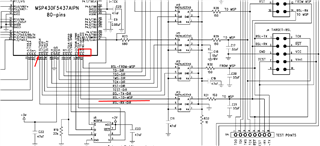
My problem is that I cannot bring UART to work. I haven't found any notes that BSL-RX and TX pins cannot be used for user application as UART line.
Currently, I use Replicator430F from slau320 repository as a base code.
Here is my UART code:
#include "Config430.h"        // High-level user input
#include "driverlib.h"
#include "debug_log.h"

#ifdef MCLK_18MHZ
    #define MCLK_FREQ 18000000 // 18 MHz
#else
    #define MCLK_FREQ 12000000 // 12 MHz
#endif

#define UART_BASE USCI_A0_BASE
#define UART_BAUD_RATE 115200

bool is_init_done = 0;

void Debug_UART_Init(void)
{
    if (!is_init_done)
    {
        GPIO_setOutputLowOnPin(GPIO_PORT_P2, GPIO_PIN0);
        // Configure UART pins: P3.4 = UCA0TXD, P3.5 = UCA0RXD
        GPIO_setAsPeripheralModuleFunctionInputPin(
            GPIO_PORT_P3,
            GPIO_PIN4 | GPIO_PIN5
        );

        // Calculate baud rate settings
        uint32_t clockSource = MCLK_FREQ;
        uint32_t baudRate = UART_BAUD_RATE;
        uint32_t n = clockSource / baudRate;  // ~ 104.1667
        uint32_t brdiv = n / 16;              // = 6
        uint32_t remainder = n - (brdiv * 16); // ~ 8.1667
        uint32_t firstMod = (uint32_t)( ( (float)remainder / 16.0 ) * 16 + 0.5 ); // ~ 8
        uint32_t secondMod = 0; // Approximation for minimal setup

        // Initialize UART configuration structure
        USCI_A_UART_initParam uartParams = {
            .selectClockSource = USCI_A_UART_CLOCKSOURCE_SMCLK,
            .clockPrescalar = 6, // brdiv,
            .firstModReg =  8, // firstMod,
            .secondModReg = 0, // secondMod,
            .parity = USCI_A_UART_NO_PARITY,
            .msborLsbFirst = USCI_A_UART_LSB_FIRST,
            .numberofStopBits = USCI_A_UART_ONE_STOP_BIT,
            .uartMode = USCI_A_UART_MODE,
            .overSampling = USCI_A_UART_OVERSAMPLING_BAUDRATE_GENERATION
        };

        // Initialize UART module
        if (STATUS_FAIL == USCI_A_UART_init(UART_BASE, &uartParams)) {
            // Initialization failed
            while(1);
        }

        // Enable UART module
        USCI_A_UART_enable(UART_BASE);

        // Clear any pending interrupts
        USCI_A_UART_clearInterrupt(UART_BASE, USCI_A_UART_RECEIVE_INTERRUPT);

        is_init_done = 1;
    }

}

void Debug_UART_Log(const char* message)
{
    while(*message)
    {
        USCI_A_UART_transmitData(UART_BASE, *message++);
    }
}void runProgramm(void)
{
//! \brief Data pointer
word p;
//! \brief Buffer, used for memory read with ReadMemQuick()
word ReadArray[0x40];
/*------------------------------------------------------------------------------------------------------*/
/* 1. | Initialize host MSP430 (on Replicator board) & target board */
/*------------------------------------------------------------------------------------------------------*/
InitController(); // Initialize the host MSP430F5437
ShowStatus(STATUS_ACTIVE, 0); // Switch both LEDs on to indicate operation.
Debug_UART_Init();
Debug_UART_Log(test_msg);

Hi,
I still not understanding what you are trying to do here. But looked into your code. Can you try below code to configure the P3.4 and P3.5 pin as UART function?
P3SEL |= GPIO_PIN4 + GPIO_PIN5;
instead of calling GPIO_setAsPeripheralModuleFunctionInputPin()
Best regards,
Cash Hao
Hello,
Thank you for your response!
I have tried to set pins in the following way as well, no result.
I'm just trying to setup UART peripheral, in application code based on Replicator430 code(http://www.ti.com/lit/zip/slau320)
**Attention** This is a public forum