This thread has been locked.

If you have a related question, please click the "Ask a related question" button in the top right corner. The newly created question will be automatically linked to this question.

Some quesitons with 2-wire JTAG on "Unknown device" error

Other Parts Discussed in Thread: MSP430G2302

Hi,

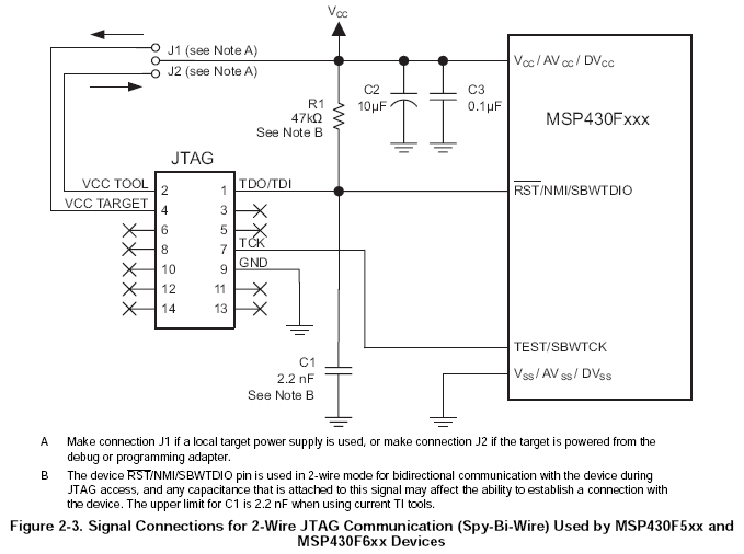
We have built a customized board with MSP430G2302 and the board has its own power supply. The debugging connection was designed to be Spy-Bi-Wire.

We followed the 2-wire connection scheme in http://processors.wiki.ti.com/index.php/JTAG_(MSP430). However, CCS gave us “Error connecting to the target: Unknown device” error.

After comparing the schematics with ours, we noted that we missed the 47Kohm R1, 2.2nF C1 and the 330ohm R2. We could do some jump wiring quickly to add these connections to the board however the board space is limited. So which of these missed wires components are imperative? I guess R1?

We also have some questions for the 2-wire schematics. Footnote B says that C1 has 2.2nF upper limit. Isn’t the larger the better?

Footnote C says when fuse blow is not used, R2=0 and “connection TEST/VPP must not be made”, and this expression is quite confusing. Does it basically mean that if fuse blow is not needed, TCK and the TEST/VPP network should be disconnected?

The last question is that in CCS’s target configuration we found no option toggling 2-wire or 4-wire connection. So does MSP-FET430UIF detect 2-wire/4-wire automatically?


John

  • John Mielke said:
    So which of these missed wires components are imperative? I guess R1?

    The R1 pull-up is required to keep the reset line high when the MSP-FET430UIF isn't connected. When the MSP-FET430UIF is connected not sure if the reset is driven as totem-pole (will work without R1) or as an open-collector (won't work without R1).

    Not connecting C2 shouldn't stop the MSP-FET430UIF detecting the MSP430G2302. It is used to hold the MSP430G2302 in reset when the MSP-FET430UIF isn't connected and the VCC is rising slowly.

    John Mielke said:
    Footnote B says that C1 has 2.2nF upper limit. Isn’t the larger the better?

    As Footnote B tries to explain, during Spy-Bi-Wire operation the RST/NMI/SBWTDIO pin is used for bi-directional communication and if C1 is too large it can stop the communication.

    John Mielke said:
    Footnote C says when fuse blow is not used, R2=0 and “connection TEST/VPP must not be made”, and this expression is quite confusing. Does it basically mean that if fuse blow is not needed, TCK and the TEST/VPP network should be disconnected?

    If fuse blow isn't required then connect the TCK pin 7 on the JTAG connector to the TEST/SBWTCK pin of the MSP430G2302 as per the following diagram:


    (This diagram is from the MSP430 Hardware Tools User's Guide SLAU278J for the 5 and 6 series devices which use a flash security fuse, but should apply to 2 series devices if there is no need to blow the 2 series security fuse).

    John Mielke said:
    The last question is that in CCS’s target configuration we found no option toggling 2-wire or 4-wire connection. So does MSP-FET430UIF detect 2-wire/4-wire automatically?

    The MSP430.dll used to communicate with the MSP-FET430UIF defaults to an automatic selection of 2-wire/4-wire. The MSP430.dll has an API to allow the communication to be forced to 2-wire or 4-wire, rather than the automatic selection, but CCS doesn't provide a method to force the 2-wire or 4-wire communication.

  • Chester,

    I followed the schematic you attached and the connection was successful, thanks!  Thanks also for your answer on R1, C1 and MSP430.dll mechanism.

    John

  • John Mielke said:
    Footnote B says that C1 has 2.2nF upper limit. Isn’t the larger the better?

    Yes. Only that it acts as a low-pass on the SBW signal and therefore needs to be kept small.

    However, if you separate the R1/C1 combo  from the RST line through another series resistor of, say, 1k, this disconnects the (unwanted) low-pass from the SBW signal while still serving its purpose of keeping RST low on power-up. Then you may use a larger capacitor (100nF) for C1.

**Attention** This is a public forum