This thread has been locked.

If you have a related question, please click the "Ask a related question" button in the top right corner. The newly created question will be automatically linked to this question.

MSP430F5529 AVCC1 decoupling capacitor

Other Parts Discussed in Thread: MSP430F5529

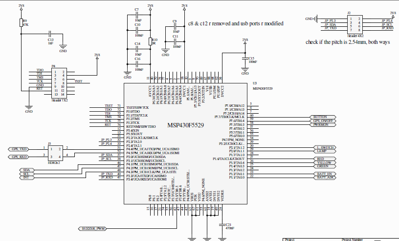
I am developing a custom board using MSP430F5529 and I am confused about the selection of decoupling capacitors for the "AVCC1". On the launchpad (http://www.ti.com/lit/ug/slau533/slau533.pdf) it has just connected 100nF. But on expermental board (http://www.ti.com/lit/ug/slau330a/slau330a.pdf) there are two 10uF & two 100nF capacitors connected. On my board I've an accelerometer & GSM module.

Do you have a recommendation on which reference to follow?

My second question is, due to space limit I have decided to not use any external oscillator. I don't have and component that requires special timing. It is a big disadvantage to not add the 32k Oscillator?

Thank you in advance

  • Low cost devboards as Launchpad usually are "as low cost as possible" design. LP decoupling solution does not give any room to play with AVCC bus filtering. On experimenter's board you can change R2 with couple ohms resistor - to have better noise filtering on AVCC, if needed. Both solutions are right depending on requirements for AVCC bus noise level. For instance if you stop digital part while run analog part like ADC then you don't need heavy decoupling on AVCC bus and you will be fine with 100nF alone. If you need just for example 9bits of ADC reading perhaps you can live with noisy AVCC too. It all depends.

    samuel shimelis yigezu said:
    I don't have and component that requires special timing. It is a big disadvantage to not add the 32k Oscillator?

    msp430 can live without 32k oscillator. So if you don't want it - don't use it :)

  • Sorry for the delayed response, I didn't get notification email of your reply.

    The ADC that I have is a battery measurement circuit which will not need that much precision. To be on the safe side, I will use the one with noise filtering, but is there any documentation that I can refer to, to decide on the selection? I didn't find much information on the datasheet nor on the familiy user's guide.

  • samuel shimelis yigezu said:
    I will use the one with noise filtering, but is there any documentation that I can refer to, to decide on the selection? I didn't find much information on the datasheet nor on the familiy user's guide.

    Supply decoupling, noise-aware PCB design guidelines are not msp430-specific. You can find them all around on TI site. Look ADC application notes "PCB Layout Guidelines" os something like that. Supply decoupling and ground (plane) guide possibly can be discussed separately. You just have to look for it, use search.

  • the 10µF/100nF combo is use to have a low ESR ceramic cap combined with a high-capacitance (but rather high ESR) tantalum cap (tantalums have very low leakage). TO drive AVCC, a 10 to 100 ohms series resistor is also recommended. This gives good decoupling against noise, ripple and spikes on VCC (mainly the 100nF) and also provides some backup for load changes in the analog part (the tantalum).

    The same combo is also recommended for decoupling the reference output (if enabled), on older MSPs it is required for reference in any case to have it stable.

    samuel shimelis yigezu said:
    I don't have and component that requires special timing. It is a big disadvantage to not add the 32k Oscillator?

    If you do not have specific timing requirements regarding absolute precision, you may use the internal REFO instead. Do you use UART? Here the precision of the REFO is usually sufficient, but depending on the tolerances on the other side, it may become critical. Especially if you have varying temperature or supply voltage.

  • Here is the schematic diagram of my design. As you said I will consider the 0 ohm resistor by 10-100 ohm. But due to space issues, I did not use tantalum caps for the big 10uF, rather I used multilayer ceramic caps like this one "CGA4J3X5R1A106K125AB". I hope it will not be a problem.

    Regarding the UART I have a GSM module that works on 4800 baudrate. I have different voltage levels on the board but the supply to the microcontroller is not varying(if that's what u meant). What is your opinion on these issues?

  • samuel yigezu said:
    due to space issues, I did not use tantalum caps for the big 10uF, rather I used multilayer ceramic caps

    Hmmm, a 10µF ceramic cap likely isn't smaller than a 5V 10µF tantalum. But usually way more expensive. Sure, it is better (and maybe you can spare the  100nF then, if the 10µF has comparable ESR).

    But I agree, the one you found is relatively cheap and also quite small, due to its only 10V, which is of course sufficient.

    4800Bd shouldn't be a problem with the internal REFO precision.

**Attention** This is a public forum