Hi everyone,
this FAQ addresses the most common questions one might have about the new MSP432™ MCU. The main topics currently covered in this FAQs are:
- MSP432 MCU Overview
- List of MSP432 microcontroller resources
- Key features of MSP432 MCU
- More MSP432 MCU technical details
- MSP432 Microcontroller Tools, IDE & Debug
- MSP432 Microcontroller LaunchPad
- EnergyTrace™ Software and Technology
- TI Cloud Development Tools
| IMPORTANT VERSION INFORMATION for Rev. C devices and Red MSP-EXP432P401R Launchpads |
| If you are using Rev. C MSP432 microcontrollers, there are minimum version requirements for CCS, IAR, Keil and SimpleLink™ MSP432 software development kit (SDK). Please see www.ti.com/xms432support and the app note Moving From Evaluation to Production With MSP432P401x MCUs for more information. |
MSP432 MCU Overview
Q: What is Texas Instruments announcing?
A: TI is announcing an expanded MSP portfolio including a new family of 32‐bit processors built on the ARM Cortex‐M4F core. The first family includes the MSP432P401x MCUs with 48MHz speed, 1MSPS 14‐bit ADC, up to 256KB flash, up to 64kB RAM and low‐power operation of only 95uA/MHz active and 850nA in standby with RTC.
Q: What is MSP?
A: MSP is TI’s low‐power MCU portfolio. It includes two platforms: 16‐bit ultra‐low‐power MSP430™ MCUs and 32‐bit low power and performance MSP432 MCUs.
Q: Why is TI moving its MSP430 MCU family from a proprietary core to an industry‐standard core?
A: The 16‐bit MSP430 MCUs are on a TI‐developed (proprietary) core and will continue to be developed and produced for all of our customers needing ultra‐low power MCUs. The new MSP432 MCU family is designed for customers who care about low‐power consumption, but need added performance (32‐bits and 48MHz) or are looking to take, or already have taken, their designs to the industry‐standard ARM Cortex‐M core.
Q: Is TI changing its focus for MSP430 towards performance instead of low‐power?
A: No. Low‐power remains at the heart of MSP’s brand, expertise and value proposition to our customers. The MSP architecture is optimized for low‐power; however the new MSP432 MCU platform will also include high performance features.
Q: Where does the MSP432 MCU platform fit within TI’s MCU portfolio, within the MSP MCU portfolio?
A: The MSP432 MCU platform is part of the TI’s low‐power MSP MCU portfolio. Within MSP, MSP432 MCUs are part of the “Low‐Power + Performance” family (which also includes the 16‐bit MSP430F5x/F6x series). MSP also contains the “Ultra‐Low Power” family that includes TI’s FRAM MCU products and the “Security + Communication” family that includes RF430 SoCs with an integrated 13.56MHz RF radio.
Q: Why is TI using an ARM Cortex‐M4F core in its MSP MCU portfolio?
A: TI’s MSP432 MCUs are a differentiated low‐power Cortex‐M‐based MCU that provide performance benefits to existing MSP430 customers and enable existing ARM developers to become part of the MSP family. With more than 20 years of low‐power expertise, TI’s MSP MCU team is best equipped to create a low‐power general purpose Cortex–M solution with a focus on high performance, analog integration and ease of use. MSP is recognized as a trusted, low‐power leader with an ecosystem that enables developers of all experience levels.
Q: What is the SDK?
A: The MSP432 software development kit (SDK) is a comprehensive software package that enables engineers to quickly develop highly functional applications on Texas Instruments MSP432 microcontrollers (MCUs). The MSP432 SDK is comprised of multiple compatible software components including RTOS, drivers, and middleware as well as examples of how to use these components together. In addition, examples are provided to demonstrate the use of each functional area and each supported device and as a starting point for your own projects.
Q: What is a plug-in?
A: Plugins are intended to extend functionality of each individual base SDK to include specialized use-cases. These specialized use cases can range anywhere from adding wireless functionality to extending a base SDK's example base.
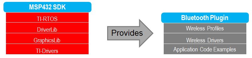
While all of the plugins have the same basic structure and look-and-feel of an SDK, they are not meant as standalone applications and rely heavily on components from the base SDK. The SimpleLink MSP432 SDK Bluetooth Plugin, for example, relies heavily on the TI-Drivers, TI-RTOS, DriverLib, and GraphicsLib components from the base SDK. A high level block diagram of these dependencies can be seen in the image below:
List of MSP432 Resources
For more information on the MSP432 MCU device, go to:
- The MSP432 MCU product folder
- Getting Started with MSP432P4x page at www.ti.com/msp432.
- A comprehensive list of links to many useful documents/SW/and other contents here. 8168.MSP432_Collateral_List_External.pdf
- SimpleLink™ MSP432™ SDK
- MSP432 MCU Application Notes: on ti.com
Key features of MSP432 MCUs
A: The MSP432 microcontroller is designed for customers looking for high performance, analog integration or general purpose processing. Key features within the MSP432 MCU portfolio include a 48MHz ARM Cortex‐M4F core with floating point unit (FPU); Driver Lib in‐ROM; wide voltage range from 1.62‐3.7 V; simultaneous flash read/write; 128‐bit flash buffer and pre‐fetch; selectable RAM retention; 64 KB RAM, 1MSPS ADC14; 8‐ channel DMA; memory protection unit; integrated LDO and DC/DC; NVIC with tail‐chaining; tunable DCO; peripheral and SRAM memory bit‐band; 20mA high drive I/O; 32‐bit timer; JTAG security and advanced IP protection; UART; I2C; SPI Bootstrap Loader and TI’s EnergyTrace+™ Technology.
A: Yes. MSP432 MCUs can operate up to 48MHz across the entire voltage range, even at the minimum supply voltage of 1.62V. Flash access is also available at 1.62V.
A: MSP432 MCUs offer wakeup from LPM3 via the RTC, WDT and GPIOs. This is to ensure current consumption is minimized in LPM3, by gating the rest of the peripherals. As a result, TI was able to achieve 850nA in LPM3. TI is working on future MSP432 MCUs that offer wake-up capabilities from additional interfaces and peripherals.
A: ULPBench is an ultra‐low power benchmark (ULPBench) from the Embedded Microprocessor Benchmark Consortium (EEMBC), who developed the CoreMark standard for evaluating processor performance across architectures. Similarly, ULPBench provides a standard way to compare power performance on any MCU, independent of architecture. The new MSP432 MCUs are the latest advancement in TI’s ultra‐low‐power innovation, delivering a best‐in‐class ULPBench score of 192.3 – outperforming all other Cortex‐M3 and Cortex‐M4F MCUs on the market.
A: The ULPBench benchmark from EEMBC includes considerations of power modes, usage of a real-time clock or timer-triggered wakeup, and a standardized computational workload, which provide a great starting point for comparing application-level power consumption across microcontrollers. That said, it includes a single application use-case and further analysis is required to evaluate microcontrollers in your specific application, which may require a different active/low power mode duty cycle than that provided by the benchmark. TI’s FRAM MCU portfolio and MSP432 MCU platform each deliver a unique set of benefits that customers can leverage in their applications – focusing on performance and/or low-power. EEMBC’s EnergyMonitor tool can be leveraged in your application to measure power consumption over time and can even be used for power-debugging once the right microcontroller is selected for an application.
A: MSP430 MCUs have unmatched brand recognition worldwide. TI worked to retain much of the original MSP430 naming; however it changed the ‘430’ to ‘432’ to reflect the new 32‐bit performance capability. The next digit in the part number indicates the series – ‘P’ meaning “Low power + Performance” series. The next digit indicates the family – the first of which in the ARM Cortex‐M4F portfolio is to the ‘4’ family. The full MSP432 MCU part numbering scheme is available online.
A: Start evaluating MSP432 MCUs immediately with a target board (MSP‐TS432PZ100) or a low‐cost LaunchPad rapid prototyping kit (MSP‐EXP432P401R) with on‐board emulation. Both kits are available from the TI Store.
A: There is training and application notes available for MSP432 MCU.
- SimpleLink Academy
- MSP432 MCU Training Series
- MSP432 Fundamental Workshop for CCSv7
- Upcoming: Stay tuned for more information on future Webinar events.
More MSP432 Technical Details
A: MSP432 header file includes both MSP & CMSIS definitions as well as CMSIS intrinsics & core functions. CMSIS DSP libraries are also fully compatible with MSP432 MCU.
A: The default MSP432 MCU Flash BSL supports the UART, I2C and SPI peripheral interfaces (unlike previous BSL versions that only supported one peripheral interface). The command structure is the same as previous MSP430 MCU BSLs.
A: BSL is flash-based BSL similar to MSP430 MCU (5xx/6xx). You can customize the BSL, or you can permanently disable it by erasing the BSL memory.
A: One of the most important functions of the SYSCTL module is the security control of the device. MSP432 microcontrollers are capable of securing the devices against access from the debugger (Full chip security) similar to MSP430 MCU. In addition, MSP432 controllers provide security control for different configurable regions of the device. Application can choose to load a secure code (IP software/middleware) into the device Flash memory. There are 4 IP-protected regions with executable IP blocks that are protected from read/write access. Encrypted field firmware update is supported for IP protection regions.
All JTAG (debugger) accesses to secure memory zones are treated as unauthorized and also return an error response. The feature is available via IDE or as part of your application to completely block future application JTAG accesses to the device. After locking the JTAG, only BSL access is possible. Device is only recoverable after a complete device erase removing all data & secure information on the device.
A: 2 banks, each with 128kB and consisting of 32 x 4kB sectors.
A: 8 banks, each with 8kB.
A: For both questions: MSP432 microcontrollers (flash) are fully erased when shipped to customers. When the flash is empty (specifically when the reset vector + SP are empty), boot code automatically puts the device in BSL mode. If there’s no BSL activity after some time, device automatically goes into LPM4.5 mode, consuming <100nA.
MSP432 Tools, IDE & Debugging FAQs
A: When using the TI compiler, the CCS code size limit is 32kB for MSP432 MCUs. The limit is independent of the debugger used in the system (stand-alone or on-board debugger such as the MSP432 Microcontroller LaunchPad). There is no code size limit when using the ARM GCC Compiler inside CCS. You can download/update TI as well as ARM GCC compilers from the CCS App Center.
An updated list can be found here. If you are using the MSP-EXP432P401R LaunchPad, you can use the XDS110-ET on-board emulator.
- In CCS, select the XDS110 USB Debug probe.
- In IAR or Keil, select the CMSIS-DAP, or TI XDS debug probe.
If you are using the MSP-TS432PZ100 target socket board or develop your own MSP432 Microcontroller application, or just want to use an external debugger with the MSP-EXP432P401R LaunchPad, you can use one of the following debuggers.
|
Debugger
|
CCS
|
IAR
|
Keil
|
|
TI XDS200, XDS100v2, XDS100v3
|
✓
|
✓
|
|
|
Segger J-Link
|
✓
|
✓
|
✓
|
|
IAR I-jet
|
✓
|
||
|
Keil uLink2/Pro
|
✓
|
||
|
XDS110-ET (on-board LaunchPad)
|
✓
|
✓
|
✓
|
|
MSP430 MCU Flash Emulation Tool
|
✓
|
✓
|
|
A: Certain serial terminal programs such as HTerm or the CCS built-in terminal might not work with the MSP432 LaunchPad at specific baudrates, resulting in the software not being able to open the virtual COM port or in the baud rate getting configured incorrectly. An issue with the LaunchPad’s emulator firmware has been identified and will be fixed in the next release. Until the update is available, use Tera Term, ClearConnex, or HyperTerminal instead or reduce the baud rate to speeds of 38,400 baud or lower.
A: It has been observed that when the MSP432 LaunchPad is connected to USB3.0 ports provided by a certain combination of USB3.0 host controller hardware and associated device drivers that the IDE is unable to establish a debug session with the LaunchPad, resulting in an error message like “CS_DAP_0: Error connecting to the target: (Error -260 @ 0x0) An attempt to connect to the XDS110 failed.” in the case of Code Composer Studio. In this case the CCS-provided low-level command line utility ‘xdsdfu’ will also not be able to establish a connection with the LaunchPad.
A: Check the following:
- Do the baud rate in the host’s terminal application and the USCI settings match?
- Are the appropriate jumpers in place, on the isolation jumper block?
- Probe on RXD and send data from the host. If you don’t see data, it might be a problem on the host side.
- Probe on TXD while sending data from the MSP432. If you don’t see data, it might be a configuration problem with the USCI module.
- Consider the use of the hardware flow control lines (especially for higher baud rates).
A: EnergyTrace+ technology for MSP432 MCUs is an energy‐based code analysis tool that measures and displays the application’s energy profile and helps to optimize it for ultra‐low‐power consumption. This technology provides developers with a real‐time tool that monitors power consumption data within ±2 percent accuracy.
Q: Will TI expand support for its Grace™ software?
MSP432 LaunchPad FAQs
A: Yes. TI is also adding support for existing BoosterPacks to work with the new MSP432 LaunchPad, including the CC3100 Wi-Fi BoosterPack, BLE BoosterPack from Anaren, TRF7979A NFC BoosterPack, Kentec QVGA Display BoosterPack, Fuel Tank battery BoosterPack , the Sharp96 Display BoosterPack, and the CC2650 BoosterPack.
A: Yes! We encourage you to do so. The design files are on ti.com.
A: This LaunchPad provides more functionality, and this means using a device with more pins. Sockets for devices with this many pins are too expensive for the LaunchPad’s target price.
A: For several reasons. A major feedback item on previous LaunchPads was the desire for female headers instead of male ones. But simply using female instead is problematic, because compatibility with existing BoosterPacks would be lost, and some people prefer male headers. So, adding female headers without removing male ones satisfies both preferences. It also allows more flexibility in stacking BoosterPacks and other LaunchPads.
The down side to this approach is perhaps that the board doesn’t sit flat. But while a USB cable is attached (the usual development model), it tends to not sit flat anyway. For those wishing it to sit flat, holes were drilled in the corners, so that standoffs could be fastened. Rubber bumper feet also should work.
EnergyTrace Technology FAQs
A: The sampling frequency depends on the debugger and the selected debug protocol and its speed setting. It typically ranges from 1 kHz (for example, when using the XDS110 SWD interface) up to 3.2 kHz (for example, when using the JTAG interface set to FAST). The debugger polls the state information of EnergyTrace+ from the device status information. Depending on the sampling frequency, a short or fast duty cycle active peripheral state may not be captured on the State graph. In addition, the higher sampling frequency affects the device energy consumption under EnergyTrace.
A: The sampling frequency to measure the energy consumption is the same independent of which debug protocol or speed and is approximately 4.2 kHz in Free Run mode.
A: The power values shown in the Power graph are derived (that is, calculated) from the accumulated energy counted by the measurement system. When the target is consuming little energy, a small number of energy packets over time are supplied to the target, and the software needs to accumulate the dc-dc charge pulses over time before a new current value can be calculated. For currents under 1 µA, this can take up to one second, while for currents in the milliamp range, a current can be calculated every millisecond. Additional filtering is not applied so that detail information is not lost. Another factor that affects the energy (and with it, the current) that is consumed by the target is periodic background debug access during normal code execution, either through capturing of States information or through breakpoint polling. Try recording in Free Run mode to see a much smoother Power graph.
A: During program counter trace, various factors affect the number of times a function is detected by the profiler over time. The microcontroller code could benefit from the internal cache, thus executing some functions faster than others. Another influencing factor is memory wait states and CPU pipeline stalls, which add time variance to the code execution. An outside factor is the sampling frequency of the debugger itself, which normally runs asynchronous to the microcontroller's code execution speed, but in some cases shows overlapping behavior, which also results in an unequal function run time distribution.
A: During transitions from active mode to low-power mode, internal device clocks are switched off, and occasionally the state information is not updated completely. This state is displayed as <Undetermined> in the Profile window, and the States graph shows a gap during the time that the <Undetermined> low-power mode persists. The <Undetermined> state is an indication that your application has entered a low-power mode, but which mode cannot be accurately determined. If your application is frequently entering low-power modes, the <Undetermined> state will probably be shown more often than if your application only rarely uses low-power modes.
A: The energy measurement method used on the hardware counts dc-dc charge pulses over time. Energy and power are calculated from the energy over time. Due to statistical sampling effects and charge and discharge effects of the output voltage buffer capacitors, it is possible that minimum and maximum values of currents vary by some percent, even though the program is identical. The captured energy, however, should be almost equal (in the given accuracy range).
A: The energy measurement circuit is directly supplied from the USB bus voltage, and thus it is sensitive to USB bus voltage variations. During calibration, the energy equivalent of a single dc-dc charge pulse is defined, and this energy equivalent depends on the USB voltage level. To ensure a good repeatability and accuracy, power the debugger directly from an active USB port, and avoid using bus-powered hubs and long USB cables that can lead to voltage drops, especially when other consumers are connected to the USB hub. Furthermore the LDO and resistors used for reference voltage generation and those in the calibration circuit come with a certain tolerance and ppm rate over temperature, which also influences accuracy of the energy measurement.
A: Both EnergyTrace+ mode and EnergyTrace mode require the target to be supplied from the debugger. No data can be captured when the target microcontroller is externally powered.
A: Reading digital data from the target microcontroller consumes energy in the JTAG domain of the microcontroller. Hence, an average current of approximately 150 µA is measured when connecting an ampere meter to the device power supply pins. If you want to eliminate energy consumption through debug communication, switch to EnergyTrace mode, and let the target microcontroller execute in Free Run mode.
A: The most likely cause of this extra current is improper GPIO termination, as floating pins can lead to extra current flow. Also check the JTAG pins again, especially when the debugger is still connected (but idle), as the debugger output signal levels in idle state might not match how the JTAG pins have been configured by the application code. This could also lead to extra current flow.
Q: When I start the EnergyTrace+ windows through View → Other → EnergyTrace before launching the debug session, data capture sometimes does not start.
A: Enable EnergyTrace through Window → Preferences → Code Composer Studio → Advanced Tools → EnergyTrace™ Technology. When launching a debug session, the EnergyTrace+ windows automatically open, and data capture starts when the device executes. If you accidentally close all EnergyTrace+ windows during a debug session, you can reopen them through View → Other → EnergyTrace.
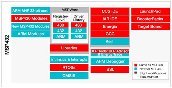
A: MSP432 MCU users can continue using the development components (identified by red boxes in the graphic below) as they’ve done in MSP430 MCUs and also utilize new options (identified in blue). The new hardware and software components to take into consideration for porting are also shown in blue. Developers can read the MSP432 Platform Porting application note to learn how to port code between 16‐bit MSP430 MCU and 32‐bit MSP432 MCU platforms.