
- Ask a related questionWhat is a related question?A related question is a question created from another question. When the related question is created, it will be automatically linked to the original question.


Hello,
I hope someone can see what I am missing! I am trying to write code to read from and write to multiple devices using I2C. Specifically, I have an MSP432 launchpad connected to multiple MSP430G2332's on a bus. I won't spend too much time describing the hardware because that works fine.
I am using the eUSCIB0 module, and in the case of a read, I first write to the address the number of the register I want to read (registers defined by me, not hardware registers). I do a repeated start and read 1 byte, though I am trying to support reading multiple bytes in the future. The problem is that it misses the first RX interrupt after the repeated start. I know this because I have a logic analyzer, and I put a breakpoint in the RX interrupt. The analyzer catches 2 bytes being read before the pause, and the first byte was not read into the received data array.
Anyway, here is my code:
uint8_t i2c_init() {

	MAP_GPIO_setAsPeripheralModuleFunctionInputPin(GPIO_PORT_P1,
	SCL_PIN | SDA_PIN, GPIO_PRIMARY_MODULE_FUNCTION); //set i/o pins to i2c module

	MAP_Interrupt_enableInterrupt(INT_EUSCIB0); //enable module interrupt

	UCB0CTLW0 |= UCSWRST;                          // put eUSCI_B in reset state
	UCB0CTLW0 |= UCMODE_3 | UCMST | UCTR;              // I2C master mode, SMCLK
	UCB0BRW = MAP_CS_getSMCLK() / I2C_SPEED;        // baudrate = SMCLK /400,000
	UCB0CTLW0 &= ~ UCSWRST;                            // clear reset register
	UCB0IE |= UCTXIE0 | UCNACKIE | UCSTPIE; // transmit and NACK interrupt enable

	return 0;
}

uint8_t getDeviceRegister(uint8_t address, uint8_t reg, uint8_t* ret_val) {

	UCB0I2CSA = address;   //Set slave address
	txPtr = txData;    //Read data array and pointer
	*txPtr = reg;       //Ready data for transmit
	rxPtr = rxData;     //Ready array to receive data

	UCB0CTLW0 |= UCSWRST;    //Reset i2c module
	UCB0CTLW0 |= UCTR;     //Start in Write mode
	UCB0CTLW1 &= ~UCASTP_M;
	UCB0CTLW1 |= UCASTP_1;    //Interrupt but no stop bit on reaching byte count
	UCB0TBCNT = 1;       //Send 1 byte before interrupt

	UCB0CTLW0 &= ~UCSWRST;
	UCB0IE |= UCTXIE0 | UCNACKIE | UCSTPIE | UCBCNTIE;

	byte_count = 1;   //Receive 1 byte (for now)
	vineSleep = 1;    //Sleep...
	status = DATA;
	UCB0CTLW0 |= UCTXSTT;   //Send start bit

	while (vineSleep)  //Sleep until done
		MAP_PCM_gotoLPM0InterruptSafe();

	if (status == NACK) {
		return NO_RESPONSE;
	}
	if (status == STOP) {
		*ret_val = rxData[0];
		return SUCCESS;
	}
	return 3;
}

void euscib0_isr(void) {

	switch (UCB0IV) {
	case NACK_IV:
		UCB0IFG &= ~UCNACKIFG;
		UCB0CTLW0 |= UCTXSTP;                  // I2C stop condition.
		status = NACK;
		vineSleep = 0;  //Wake up on NACK
		break;
	case STP_IV:
		UCB0IFG &= ~UCSTPIFG;
		status = STOP;
		vineSleep = 0;  //Wake up on stop
		break;
	case TX0_IV:
		UCB0TXBUF = *txPtr++;
		break;
	case RX0_IV:   //Breakpoint here
		if (!(--byte_count))      //When byte_count decrements from 1 to 0, send NACK and stop bit immediately
			UCB0CTLW0 |= UCTXSTP;        // I2C stop condition.
		*rxPtr++ = UCB0RXBUF;
		break;
	case BCNT_IV:
		UCB0IFG &= ~UCBCNTIFG;    //Clear flag
		UCB0IE &= ~(UCBCNTIE | UCTXIE0);   //Disable interrupt, we dont need it anymore
		UCB0IE |= UCRXIE0;           //Enable rx interrupt
		UCB0CTLW0 &= ~UCTR;     //Switch to read mode
		UCB0CTLW0 |= UCTXSTT;   /Send repeated start
		break;
	}
}
*I tried to syntax highlight it, but it didnt work.
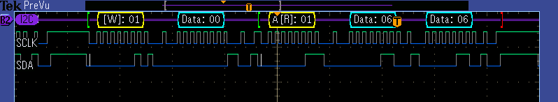
Here is the logic analyzer result, though not the case I described where I set the breakpoint.
You can see that it writes a 0x00 to device 0x01, indicating that it wants to read from register 0. There is a repeated start and read. It should only read 1 byte, since the send stop bit is set after supposedly 1 byte. But as you can see, two bytes are sent by the slave, though the first is ignored by the master.
Can anyone see what is wrong?
Thanks for your help!
Brody G
P.S. I want to note that the slave code, which I also wrote, is for the G2332 USI module. It appears to work just fine. It checks for an ACK or NACK from the master to determine whether to send another byte, and you can see the master sends an ACK after the first data byte. So it is operating correctly.


**Attention** This is a public forum

