I trailered the following code to use it for MSP430F47197.
www.ti.com/lit/an/slaa208a/slaa208a.zip
Here is my code:
#include "msp430x471x7.h"
#define SlaveAddress 0x50
#define MAXPAGEWRITE 32
int PtrTransmit;
unsigned char I2CBufferArray[100];
unsigned char I2CBuffer;
unsigned char read_val[64];
unsigned char write_val[64];
unsigned int address = 0xC0;
#define I2C_PORT_SEL P2SEL
#define I2C_PORT_OUT P2OUT
#define I2C_PORT_REN P2REN
#define I2C_PORT_DIR P2DIR
#define SDA_PIN BIT1 // SDA pin
#define SCL_PIN BIT2 // SCL pin
void InitI2C(unsigned char eeprom_i2c_address);
void EEPROM_ByteWrite(unsigned int Address , unsigned char Data);
void EEPROM_PageWrite(unsigned int StartAddress , unsigned char * Data , unsigned int Size);
unsigned char EEPROM_RandomRead(unsigned int Address);
unsigned char EEPROM_CurrentAddressRead(void);
void EEPROM_SequentialRead(unsigned int Address , unsigned char * Data , unsigned int Size);
void EEPROM_AckPolling(void);
int main(void)
{
unsigned int i;
WDTCTL = WDTPW + WDTHOLD; // Stop watchdog timer
InitI2C(SlaveAddress); // Initialize I2C module
EEPROM_ByteWrite(0x0000,0x12);
EEPROM_AckPolling(); // Wait for EEPROM write cycle
// completion
EEPROM_ByteWrite(0x0001,0x34);
EEPROM_AckPolling(); // Wait for EEPROM write cycle
// completion
EEPROM_ByteWrite(0x0002,0x56);
EEPROM_AckPolling(); // Wait for EEPROM write cycle
// completion
EEPROM_ByteWrite(0x0003,0x78);
EEPROM_AckPolling(); // Wait for EEPROM write cycle
// completion
EEPROM_ByteWrite(0x0004,0x9A);
EEPROM_AckPolling(); // Wait for EEPROM write cycle
// completion
EEPROM_ByteWrite(0x0005,0xBC);
EEPROM_AckPolling(); // Wait for EEPROM write cycle
// completion
read_val[0] = EEPROM_RandomRead(0x0000); // Read from address 0x0000
read_val[1] = EEPROM_CurrentAddressRead();// Read from address 0x0001
read_val[2] = EEPROM_CurrentAddressRead();// Read from address 0x0002
read_val[3] = EEPROM_CurrentAddressRead();// Read from address 0x0003
read_val[4] = EEPROM_CurrentAddressRead();// Read from address 0x0004
read_val[5] = EEPROM_CurrentAddressRead();// Read from address 0x0005
// Fill write_val array with counter values
for(i = 0 ; i <= sizeof(write_val) ; i++)
{
write_val[i] = i;
}
address = 0x0000; // Set starting address
// Write a sequence of data array
EEPROM_PageWrite(address , write_val , sizeof(write_val));
//Read out a sequence of data from EEPROM
EEPROM_SequentialRead(address, read_val , sizeof(read_val));
__bis_SR_register(LPM4);
__no_operation();
}
/*----------------------------------------------------------------------------*/
// Description:
// Initialization of the I2C Module
/*----------------------------------------------------------------------------*/
void InitI2C(unsigned char eeprom_i2c_address)
{
I2C_PORT_SEL |= SDA_PIN + SCL_PIN; // Assign I2C pins to USCI_B1
// Recommended initialisation steps of I2C module as shown in User Guide:
UCB1CTL1 |= UCSWRST; // Enable SW reset
UCB1CTL0 = UCMST + UCMODE_3 + UCSYNC; // I2C Master, synchronous mode
UCB1CTL1 = UCSSEL_2 + UCTR + UCSWRST; // Use SMCLK, TX mode, keep SW reset
UCB1BR0 = 35; // fSCL = SMCLK/12 = ~100kHz
UCB1BR1 = 0;
UCB1I2CSA =eeprom_i2c_address; // define Slave Address
// In this case the Slave Address
// defines the control byte that is
// sent to the EEPROM.
UCB1I2COA = 0x01A5; // own address.
UCB1CTL1 &= ~UCSWRST; // Clear SW reset, resume operation
if (UCB1STAT & UCBBUSY) // test if bus to be free
{ // otherwise a manual Clock on is
// generated
I2C_PORT_SEL &= ~SCL_PIN; // Select Port function for SCL
I2C_PORT_OUT &= ~SCL_PIN; //
I2C_PORT_DIR |= SCL_PIN; // drive SCL low
I2C_PORT_SEL |= SDA_PIN + SCL_PIN; // select module function for the
// used I2C pins
};
}
/*---------------------------------------------------------------------------*/
// Description:
// Initialization of the I2C Module for Write operation.
/*---------------------------------------------------------------------------*/
void I2CWriteInit(void)
{
UCB1CTL1 |= UCTR; // UCTR=1 => Transmit Mode (R/W bit = 0)
IFG2 &= ~UCB1TXIFG;
IE2 &= ~UCB1RXIE; // disable Receive ready interrupt
IE2 |= UCB1TXIE; // enable Transmit ready interrupt
}
/*----------------------------------------------------------------------------*/
// Description:
// Initialization of the I2C Module for Read operation.
/*----------------------------------------------------------------------------*/
void I2CReadInit(void)
{
UCB1CTL1 &= ~UCTR; // UCTR=0 => Receive Mode (R/W bit = 1)
IFG2 &= ~UCB1RXIFG;
IE2 &= ~UCB1TXIE; // disable Transmit ready interrupt
IE2 |= UCB1RXIE; // enable Receive ready interrupt
}
/*----------------------------------------------------------------------------*/
// Description:
// Byte Write Operation. The communication via the I2C bus with an EEPROM
// (2465) is realized. A data byte is written into a user defined address.
/*----------------------------------------------------------------------------*/
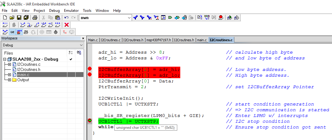
void EEPROM_ByteWrite(unsigned int Address, unsigned char Data)
{
unsigned char adr_hi;
unsigned char adr_lo;
while (UCB1STAT & UCBUSY); // wait until I2C module has
// finished all operations.
adr_hi = Address >> 8; // calculate high byte
adr_lo = Address & 0xFF; // and low byte of address
I2CBufferArray[2] = adr_hi; // Low byte address.
I2CBufferArray[1] = adr_lo; // High byte address.
I2CBufferArray[0] = Data;
PtrTransmit = 2; // set I2CBufferArray Pointer
I2CWriteInit(); UCB1CTL1 |= UCTXSTT; // start condition generation
// => I2C communication is started
__bis_SR_register(LPM0_bits + GIE); // Enter LPM0 w/ interrupts
UCB1CTL1 |= UCTXSTP ; // I2C stop condition
while(UCB1CTL1 & UCTXSTP); // Ensure stop condition got sent
}
/*----------------------------------------------------------------------------*/
// Description:
// Page Write Operation. The communication via the I2C bus with an EEPROM
// (24xx65) is realized. A data byte is written into a user defined address.
/*----------------------------------------------------------------------------*/
void EEPROM_PageWrite(unsigned int StartAddress, unsigned char * Data, unsigned int Size)
{
volatile unsigned int i = 0;
volatile unsigned char counterI2cBuffer;
unsigned char adr_hi;
unsigned char adr_lo;
unsigned int currentAddress = StartAddress;
unsigned int currentSize = Size;
unsigned int bufferPtr = 0;
unsigned char moreDataToRead = 1;
while (UCB1STAT & UCBUSY); // wait until I2C module has
// finished all operations.
// Execute until no more data in Data buffer
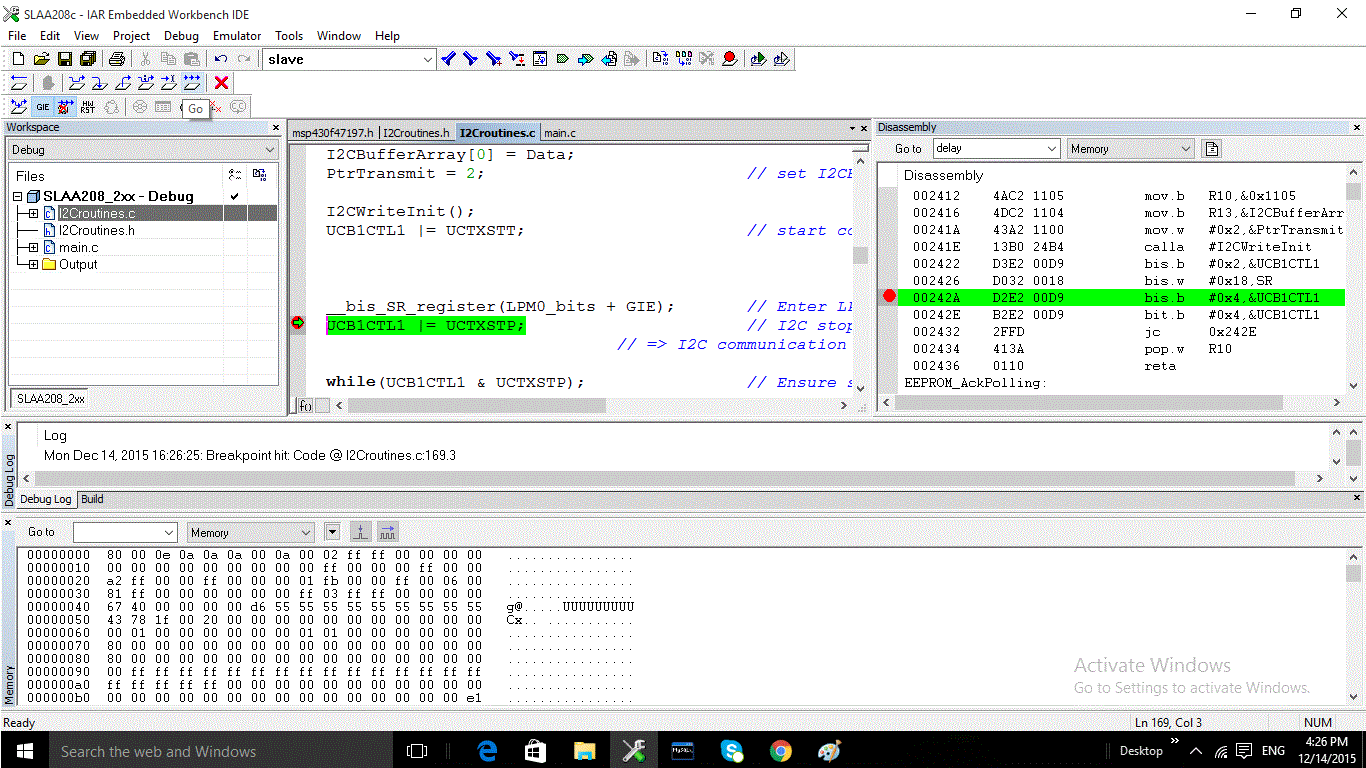
while(moreDataToRead)
{
adr_hi = currentAddress >> 8; // calculate high byte
adr_lo = currentAddress & 0xFF; // and low byte of address
// Chop data down to 64-byte packets to be transmitted at a time
// Maintain pointer of current startaddress
if(currentSize > MAXPAGEWRITE)
{
bufferPtr = bufferPtr + MAXPAGEWRITE;
counterI2cBuffer = MAXPAGEWRITE - 1;
PtrTransmit = MAXPAGEWRITE + 1; // set I2CBufferArray Pointer
currentSize = currentSize - MAXPAGEWRITE;
currentAddress = currentAddress + MAXPAGEWRITE;
// Get start address
I2CBufferArray[MAXPAGEWRITE + 1] = adr_hi; // High byte address.
I2CBufferArray[MAXPAGEWRITE] = adr_lo; // Low byte address.
}
else
{
bufferPtr = bufferPtr + currentSize;
counterI2cBuffer = currentSize - 1;
PtrTransmit = currentSize + 1; // set I2CBufferArray Pointer.
moreDataToRead = 0;
currentAddress = currentAddress + currentSize;
// Get start address
I2CBufferArray[currentSize + 1] = adr_hi; // High byte address.
I2CBufferArray[currentSize] = adr_lo; // Low byte address.
}
// Copy data to I2CBufferArray
unsigned char temp;
for(i ; i < bufferPtr ; i++)
{
temp = Data[i]; // Required or else IAR throws a
// warning [Pa082]
I2CBufferArray[counterI2cBuffer] = temp;
counterI2cBuffer--;
}
I2CWriteInit();
UCB1CTL1 |= UCTXSTT; // start condition generation
// => I2C communication is started
__bis_SR_register(LPM0_bits + GIE); // Enter LPM0 w/ interrupts
UCB1CTL1 |= UCTXSTP; // I2C stop condition
while(UCB1CTL1 & UCTXSTP); // Ensure stop condition got sent
EEPROM_AckPolling(); // Ensure data is written in EEPROM
}
}
/*----------------------------------------------------------------------------*/
// Description:
// Current Address Read Operation. Data is read from the EEPROM. The current
// address from the EEPROM is used.
/*----------------------------------------------------------------------------*/
unsigned char EEPROM_CurrentAddressRead(void)
{
while(UCB1STAT & UCBUSY); // wait until I2C module has
// finished all operations
I2CReadInit();
UCB1CTL1 |= UCTXSTT; // I2C start condition
while(UCB1CTL1 & UCTXSTT); // Start condition sent?
UCB1CTL1 |= UCTXSTP; // I2C stop condition
__bis_SR_register(LPM0_bits + GIE); // Enter LPM0 w/ interrupts
while(UCB1CTL1 & UCTXSTP); // Ensure stop condition got sent
return I2CBuffer;
}
/*----------------------------------------------------------------------------*/
// Description:
// Random Read Operation. Data is read from the EEPROM. The EEPROM
// address is defined with the parameter Address.
/*----------------------------------------------------------------------------*/
unsigned char EEPROM_RandomRead(unsigned int Address)
{
unsigned char adr_hi;
unsigned char adr_lo;
while (UCB1STAT & UCBUSY); // wait until I2C module has
// finished all operations
adr_hi = Address >> 8; // calculate high byte
adr_lo = Address & 0xFF; // and low byte of address
I2CBufferArray[1] = adr_hi; // store single bytes that have to
I2CBufferArray[0] = adr_lo; // be sent in the I2CBuffer.
PtrTransmit = 1; // set I2CBufferArray Pointer
// Write Address first
I2CWriteInit();
UCB1CTL1 |= UCTXSTT; // start condition generation
// => I2C communication is started
__bis_SR_register(LPM0_bits + GIE); // Enter LPM0 w/ interrupts
// Read Data byte
I2CReadInit();
UCB1CTL1 |= UCTXSTT; // I2C start condition
while(UCB1CTL1 & UCTXSTT); // Start condition sent?
UCB1CTL1 |= UCTXSTP; // I2C stop condition
__bis_SR_register(LPM0_bits + GIE); // Enter LPM0 w/ interrupts
while(UCB1CTL1 & UCTXSTP); // Ensure stop condition got sent
return I2CBuffer;
}
/*----------------------------------------------------------------------------*/
// Description:
// Sequential Read Operation. Data is read from the EEPROM in a sequential
// form from the parameter address as a starting point. Specify the size to
// be read and populate to a Data buffer.
/*----------------------------------------------------------------------------*/
void EEPROM_SequentialRead(unsigned int Address , unsigned char * Data , unsigned int Size)
{
unsigned char adr_hi;
unsigned char adr_lo;
unsigned int counterSize;
while (UCB1STAT & UCBUSY); // wait until I2C module has
// finished all operations
adr_hi = Address >> 8; // calculate high byte
adr_lo = Address & 0xFF; // and low byte of address
I2CBufferArray[1] = adr_hi; // store single bytes that have to
I2CBufferArray[0] = adr_lo; // be sent in the I2CBuffer.
PtrTransmit = 1; // set I2CBufferArray Pointer
// Write Address first
I2CWriteInit();
UCB1CTL1 |= UCTXSTT; // start condition generation
// => I2C communication is started
__bis_SR_register(LPM0_bits + GIE); // Enter LPM0 w/ interrupts
// Read Data byte
I2CReadInit();
UCB1CTL1 |= UCTXSTT; // I2C start condition
while(UCB1CTL1 & UCTXSTT); // Start condition sent?
for(counterSize = 0 ; counterSize < Size ; counterSize++)
{
__bis_SR_register(LPM0_bits + GIE); // Enter LPM0 w/ interrupts
Data[counterSize] = I2CBuffer;
}
UCB1CTL1 |= UCTXSTP; // I2C stop condition
__bis_SR_register(LPM0_bits + GIE); // Enter LPM0 w/ interrupts
while(UCB1CTL1 & UCTXSTP); // Ensure stop condition got sent
}
/*----------------------------------------------------------------------------*/
// Description:
// Acknowledge Polling. The EEPROM will not acknowledge if a write cycle is
// in progress. It can be used to determine when a write cycle is completed.
/*----------------------------------------------------------------------------*/
void EEPROM_AckPolling(void)
{
while (UCB1STAT & UCBUSY); // wait until I2C module has
// finished all operations
do
{
UCB1STAT = 0x00; // clear I2C interrupt flags
UCB1CTL1 |= UCTR; // I2CTRX=1 => Transmit Mode (R/W bit = 0)
UCB1CTL1 &= ~UCTXSTT;
UCB1CTL1 |= UCTXSTT; // start condition is generated
while(UCB1CTL1 & UCTXSTT) // wait till I2CSTT bit was cleared
{
if(!(UCNACKIFG & UCB1STAT)) // Break out if ACK received
break;
}
UCB1CTL1 |= UCTXSTP; // stop condition is generated after
// slave address was sent => I2C communication is started
while (UCB1CTL1 & UCTXSTP); // wait till stop bit is reset
__delay_cycles(500); // Software delay
}while(UCNACKIFG & UCB1STAT);
}
/*---------------------------------------------------------------------------*/
/* Interrupt Service Routines */
/* Note that the Compiler version is checked in the following code and */
/* depending of the Compiler Version the correct Interrupt Service */
/* Routine definition is used. */
#if __VER__ < 200
interrupt [USCIAB1TX_VECTOR] void TX_ISR_I2C(void)
#else
#pragma vector=USCIAB1TX_VECTOR
__interrupt void TX_ISR_I2C(void)
#endif
{
if(UCB1TXIFG & IFG2)
{
UCB1TXBUF = I2CBufferArray[PtrTransmit];// Load TX buffer
PtrTransmit--; // Decrement TX byte counter
if(PtrTransmit < 0)
{
while(!(IFG2 & UCB1TXIFG));
IE2 &= ~UCB1TXIE; // disable interrupts.
IFG2 &= ~UCB1TXIFG; // Clear USCI_B1 TX int flag
__bic_SR_register_on_exit(LPM0_bits); // Exit LPM0
}
}
else if(UCB1RXIFG & IFG2)
{
I2CBuffer = UCB1RXBUF; // store received data in buffer
__bic_SR_register_on_exit(LPM0_bits); // Exit LPM0
}
}
I have no idea why it stops right at
EEPROM_ByteWrite(0x0000,0x12);

Also, "Own Address" I am not too sure!!!

Any idea what the problem is?