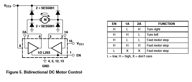
hello,my task is DC motor control in CODECOMPOSER by using msp430 ,model of G2553 and the target is making the motor in two direction,forward and backword also by using Pwm to turn that motor slow and fast by using buttons.Can you help me to write that in code composer.The MOTOR driver is L293D.
THANKS A LOT.I have a written code here but i am not sure about it,can somebody check it or help me with that code.
#include <msp430.h>
/* main.c
* Motor control using L293D
*/
#define MOTOR_1_EN BIT6
#define MOTOR_1_DIR1 BIT3
#define MOTOR_1_DIR2 BIT4
#define MOTOR_1_DIR (MOTOR_1_DIR1 | MOTOR_1_DIR2)
#define MOTOR_1_PINS (MOTOR_1_DIR1 | MOTOR_1_DIR2 | MOTOR_1_EN)
#define FOWARD_BTN BIT1
#define BACKWARD_BTN BIT2
#define STOP_BTN BIT3
#define NORMAL_SPD_BTN BIT4
#define HIGH_SPD_BTN BIT5
#define LOW_SPD_BTN BIT6
#define NORMAL_SPD 1
#define HIGH_SPD 2
#define LOW_SPD 3
#define FOWARD 1
#define BACKWARD 2
#define STOP 3
int motor_state = STOP;
int speed_state = NORMAL_SPD;
int count = 0;
void initialise()
{
/*** Watchdog timer and clock Set-Up ***/
WDTCTL = WDTPW + WDTHOLD; // Stop watchdog timer
DCOCTL = 0; // Select lowest DCOx and MODx
BCSCTL1 = CALBC1_1MHZ; // Set range
DCOCTL = CALDCO_1MHZ; // Set DCO step + modulation
/*** GPIO MOTOR Set-Up ***/
P2SEL &= ~MOTOR_1_EN; // Clear P2.6 in P2SEL (by default Xin)
P2SEL2 &= ~MOTOR_1_EN; // Clear P2.6 in P2SEL2
P2DIR |= MOTOR_1_PINS; // P2.3,P2.4,P2.6 all output
P2OUT &= ~MOTOR_1_PINS; // Clear P2.3,P2.4,P2.6
/*** GPIO BUTTON Set-Up ***/
P1DIR |= 0X01; //set all bits in P1 to input except BIT0
/*** Timer0_A Set-Up ***/
TA0CCR0 |= 12; // Counter value 1ms
TA0CCTL0 |= CCIE; // Enable Timer0_A interrupts
TA0CTL |= TASSEL_1 + MC_1; // ACLK, Up Mode (Counts to TA0CCR0)
_BIS_SR(LPM0_bits + GIE); // Enter Low power mode 0 with interrupts enabled
}
void PWM_control_motor_1(speed_state)
{
if(speed_state == HIGH_SPD)
{
P2OUT = MOTOR_1_EN;
count = 0;
}
else
{
if(speed_state == NORMAL_SPD)
{
if(count == 5)
{
P2OUT ^= MOTOR_1_EN;
count = 0;
}
}
if(speed_state == LOW_SPD)
{
if(count == 10)
{
P2OUT ^= MOTOR_1_EN;
count = 0;
}
}
}
}
void motor_1_rotate_foward()
{
P2OUT |= MOTOR_1_DIR1; // P2.3 = 1
P2OUT &= ~MOTOR_1_DIR2; // P2.4 = 0
}
void motor_1_rotate_backward()
{
P2OUT &= ~MOTOR_1_DIR1; // P2.3 = 0
P2OUT |= MOTOR_1_DIR2; // P2.4 = 1
}
void motor_1_stop_rotate()
{
P2OUT &= ~MOTOR_1_DIR; // P2.3 = 0, P2.4 = 0
}
void motor_1_action(motor_state)
{
if(motor_state == STOP)
motor_1_stop_rotate();
else if(motor_state == FOWARD)
motor_1_rotate_foward();
else if(motor_state == BACKWARD)
motor_1_rotate_backward();
}
int main(void)
{
initialise();
while(1)
{
if((P1IN & NORMAL_SPD_BTN) == 0)
speed_state = NORMAL_SPD;
if((P1IN & HIGH_SPD_BTN) == 0)
speed_state = HIGH_SPD;
if((P1IN & LOW_SPD_BTN) == 0)
speed_state = LOW_SPD;
if((P1IN & FOWARD_BTN) == 0)
motor_state = FOWARD;
if((P1IN & BACKWARD_BTN) == 0)
motor_state = BACKWARD;
if((P1IN & STOP_BTN) == 0)
motor_state = STOP;
}
}
#pragma vector=TIMER0_A0_VECTOR // Timer0 A0 interrupt service routine
__interrupt void Timer0_A0 (void)
{
count++;
PWM_control_motor_1(speed_state);
motor_1_action(motor_state);
}