This thread has been locked.

If you have a related question, please click the "Ask a related question" button in the top right corner. The newly created question will be automatically linked to this question.

Reading and Writing to FRAM2 on MSP430FR5994

Other Parts Discussed in Thread: MSP430FR5994

So I am attempting to read and write large multidimensional signed int arrays (200kB worth) to FRAM to my application. So far I have been successful in creating an array that is 6000x4 and initializing it in persistent FRAM as seen below.

#pragma PERSISTENT(FRAM_write)
signed int FRAM_write[WRITE_SIZE][COL_SIZE] = {0};


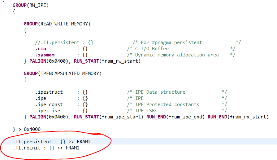
This fills up my FRAM, but i can see using the "Memory Allocation" tool in CCS that FRAM2 is only 7% full.

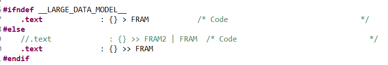
So my simple question is, how can I create an array in FRAM2 and be able to read and write data to that array from my main loop?

Thank you,

  • Hi Steven,

    By default, PERSISTENT will be placed in the lower FRAM, so it is probably using the FRAM section not FRAM2 for your array. You can check the location of FRAM_write[] by finding it in the .map file in the Debug folder in CCS, if you want to see where it got placed by the linker.

    PERSISTENT is typically placed at the very beginning of FRAM and then that first section of the FRAM memory is configured to be Read + Write permissions in the MPU, with everything else set to Read + Execute only - this is if you use the MPU tool built into CCS (found under Project > Properties) and have it set to the default of allowing the compiler and linker to decide on the memory segmentation.

    There are reasons behind this - if you want to read or write to areas with 20-bit addresses (anything above address 0x10000, so the FRAM2 section), then you have to use special 20-bit write instructions. This is done in C through the use of intrinsics like __data20_write_char() found in the compiler guide www.ti.com/lit/pdf/slau132. So it makes your code a little less nice to read (can't just access with normal array reads/writes as you would in lower memory). There's also a slight performance impact of having to use large memory accesses like these - they take more cycles - so that is the other reason to use lower memory when possible.

    However, for applications like yours where you are going to log lots and lots of data in arrays that needs to be readable and writeable, this default use-case no longer makes sense. For your case, my recommendation would be to modify your linker command file, because your data size is so large that you do need to use the upper memory where most of the FRAM space is on FR5994 - so you do need it to go in FRAM2.

    I have an earlier post helping someone with a similar issue to modify their linker file: https://e2e.ti.com/support/microcontrollers/msp430/f/166/p/461905/1712925#1712925 Let me know if you'd like more specific guidance on modifying the linker file to support your particular case, as it can be a complex topic.

    Regards,

    Katie


  • Katie,

    Thank you for your quick response! The 20-bit addresses makes a lot of sense now. 

    So here are the changes I have recently made to my C code:

    1). Updated my Properties->Build->MSP430 Compiler->Processor Options->Specify the Data Memory Model = large

    2). Initialized an data array in the FRAM in persistent:

    #pragma PERSISTENT(fram_data)
    unsigned short fram_data[0x10000] = {0};

    3). Write gyroscope data (short z_gyro_data) to FRAM2:

    while(row < array_length){
    __data20_write_short((unsigned long int)fram_data + row, z_gyro_data);
    row++;
    }

    4). After I'm done filling my array, I will want to read from it:

    row = 0;
    
    while(row < array_length){
    __data20_read_short((unsigned long int)fram_data+ row);
    row++;
    }
    

    Linker File:

    In regards to the linker file I believe I am close but probably missing something vital here. 

    1)  As you showed in https://e2e.ti.com/support/microcontrollers/msp430/f/166/p/461905/1712925#1712925 , I removed TI.persistent from the READ_WRITE_MEMORY group and assigned TI.persistent >> FRAM2. 

    GROUP(RW_IPE)
        {
    
            GROUP(READ_WRITE_MEMORY)
            {
    
                //.TI.persistent : {}              /* For #pragma persistent            */
                .cio           : {}              /* C I/O Buffer                      */
                .sysmem        : {}              /* Dynamic memory allocation area    */
            } PALIGN(0x0400), RUN_START(fram_rw_start)
    
            GROUP(IPENCAPSULATED_MEMORY)
            {
    
                .ipestruct     : {}              /* IPE Data structure             */
                .ipe           : {}              /* IPE                            */
                .ipe_const     : {}              /* IPE Protected constants        */
                .ipe:_isr      : {}              /* IPE ISRs                       */
            } PALIGN(0x0400), RUN_START(fram_ipe_start) RUN_END(fram_ipe_end) RUN_END(fram_rx_start)
    
        } > 0x4000
    
    	.TI.persistent : {} >> FRAM2

    2). I updated the LARGE_DATA_MODEL condition:

    #ifndef __LARGE_DATA_MODEL__
        .text             : {} > FRAM           /* Code                              */
    #else
        //.text             : {} >> FRAM2 | FRAM  /* Code                              */
        .text             : {} >> FRAM
    #endif

    So overall, between the C code and the linker file updates, this seems to allow me to allocate memory at address 0x010000. I can see this in the .map file, Memory browser and the Memory Allocation tool. 

    Yet, when I attempt to write to the address, nothing seems to be writing. Do you think there is an issue with the MPU not being configured correctly?

    Thanks,

    Steve

  • Hi Steve,

    Yes, the issue here is the MPU configuration. For a first test, go to Project > Properties > General go to the MSP430 MPU tab and uncheck Enable Memory Protection Unit. Then try your code - if it works, that means this was because of the MPU.

    To solve the issue, you have 2 options:
    1. I can provide information on how to modify some areas in the linker file that control the MPU setup so that it will adapt as your read/write area grows/shrinks. This will take more custom hand modification of the linker file. This is more difficult but also more flexible.
    2. (easier option, but less flexible): In that same MPU tab, select "Manually specify memory segment boundaries and access rights". Then you can select the addresses for your segments. If the only thing you have allocated into FRAM2 in your linker file is .persistent, then you can set both of the boundaries to 0x10000. Set segment 3 to read + write permission, and set segment 1 to read + execute permission. Segment 2 won't matter because in this case you set your boundaries such that there isn't a segment 2. You can also set how you want the code to react on a memory access violation - either check the box to have a PUC reset, or leave it unchecked - either way the MPU won't allow a write to the protected area (as you've seen), it's just if you want a reset as well. Finally, you can also choose if you want there to be an NMI interrupt on a violation or not (default is not) - you set this using the Enable NMI.

    For either of these, make sure that "Enable Memory Protection Unit" is checked.

    The reason option 2 is less flexible is that you are using fixed addresses, so if you want to use part of FRAM2 for something else, you'll have to update these settings to match the memory areas you are using. But, if you are just going to set aside all of FRAM2 for data, then it should be easy to just use the manual feature of the MPU tool.

    Hope this helps!

    Regards,
    Katie
  • Katie, 

    Solution #2 worked perfectly for my application thank you! I was able to follow your recommendations and I am now able to read and write to all of FRAM2 using the __data20_write_short() and __data20_read_short() functions. 

    For others reading this, I was able to write and read to FRAM2 (both PERSISTENT and NOINIT) by doing the following:

    #1. Edit the linker file (lnk_msp430fr5994.cmd).

    #2.  Modify they MPU Settings.

    #3. Update Processor Options to the following.


    #4. Declare the PERSISTENT and NOINIT. Here I initialize a Persistent "fram_data" array that was 0x186A2 in length all to 0. The NOINIT numLogFiles will save the memory content at this address after a power cycle. 

    #pragma PERSISTENT(fram_data)
    unsigned short fram_data[0x186A2] = {0};
    
    #pragma NOINIT(numLogFiles)
    unsigned short numLogFiles;

    #5. To write to FRAM2 memory:

    __data20_write_short((unsigned long int)fram_data, data_you_want_to_write);

    #6. To read from FRAM2 memory:

    __data20_read_short((unsigned long int)fram_data);

    Hopefully this helps! Thanks again Katie!

    -Steve


  • Hi Steve,

    I'm so glad I was able to help. And thanks so much for posting back the details for others - it's really helpful! :-)

    Regards,
    Katie

**Attention** This is a public forum