This thread has been locked.

If you have a related question, please click the "Ask a related question" button in the top right corner. The newly created question will be automatically linked to this question.

MSP430F149: Timer working as PWM generator malfunction.

Part Number: MSP430F149

Hi, Sir or Madam

I am trying to generate SPWM with Time A on MSP430F149. But it has malfunction. The output does not toggle as programmed on the 3/4 cycle time. 

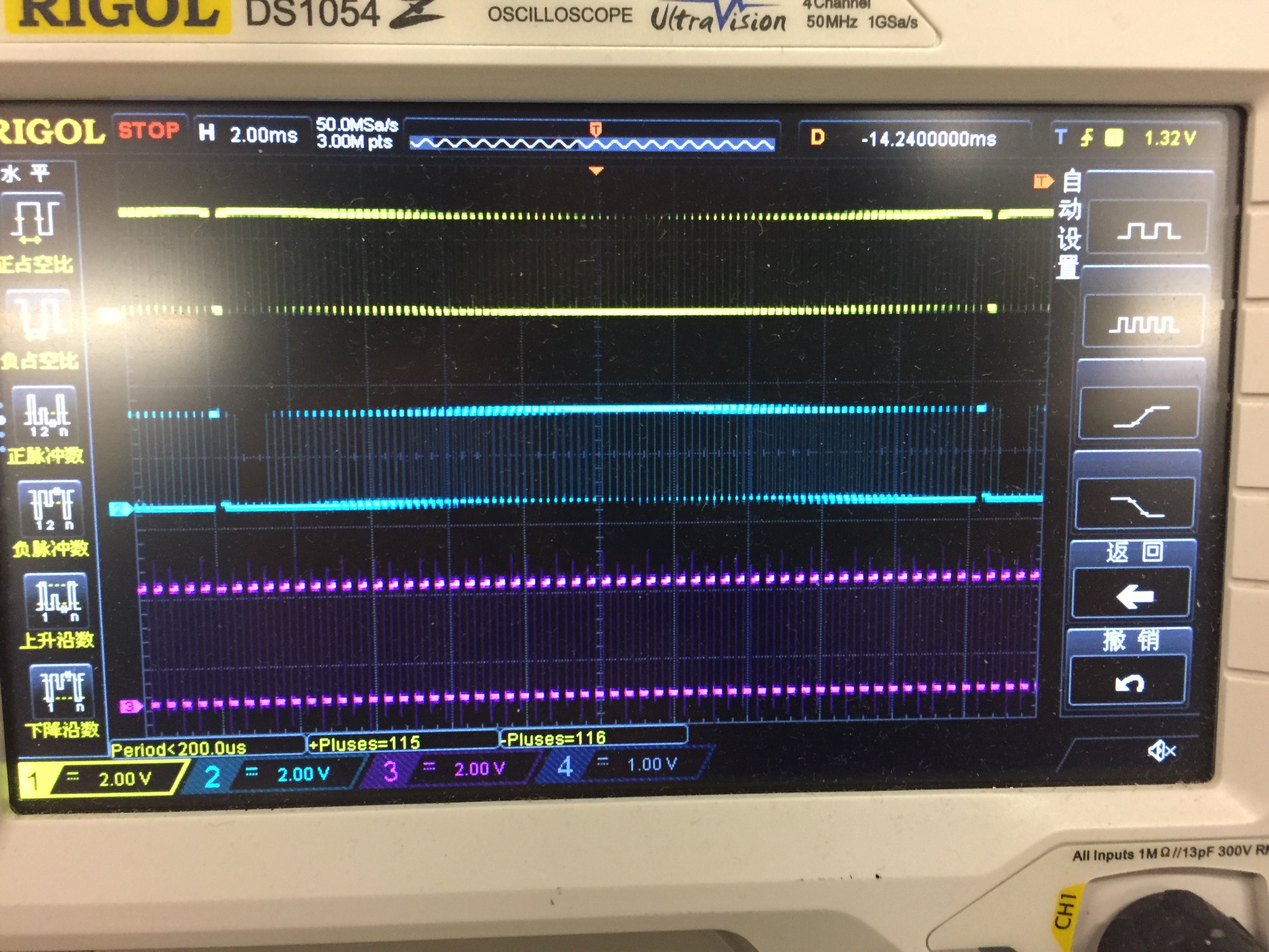
TACLK is 2MHz. The purple channel is output for TA0, toggled everytime counted to TACCR0, 402.

Yellow channel is for TA1, blue for TA2. 

You can see the dutycycle of each period is changing as sin function. But there is a period on both yellow and blue channel with 100% duty cycle. And that is wrong. I don't know why.

Do you know why? How to fix it? I can send you the code on email.

  • Since the TimerA CCRs aren't buffered, there are hazards (races) with updating the CCRs near 0% and 100% duty cycle. The symptom is usually a "glitch" period such as the one you are seeing.

    The race has to do with updating the CCR after the counter (TAR) has counted past it. If you consistently update either before or after, you won't see a glitch, but this consistency is difficult to manage at the boundaries. 

    There aren't trivial remedies, but if you think through the possible orderings you can usually get what you want. One possibility is to update the CCR on CCIFG rather than TAIFG. A good choice of OUTMOD helps.

    If you have the option, switching to using TB0 rather than TA0 can avoid these hazards, since with TB0 the hardware will update the CCRs reliably at a well-known time.

  • Hi, thanks for your reply.

    CCR0 is always 402. 

    I updated CCR1 and CCR2 in Timer A0 interrupt service function. So I think I am using TACCR0 CCIFG to update the TACCR1 and CCR2.

    When I update the CCR1 and CCR2, since CCR0>=CCR1=CCR2=6 or 9, so CCR1 and CCR2 are updated after the counter (TAR) has counted past them.

    And the  "glitch" period always occures on the same position(CCR1=9 CCR2=6) every time. Does it mean something?

    Thanks

  • > since CCR0>=CCR1=CCR2=6 or 9, so CCR1 and CCR2 are updated after the counter (TAR) has counted past them

    Almost. CCR0 isn't the issue. Rather it is the (execution) time it takes from the moment of the CCR0 interrupt to the moment you update the CCR (each of them). This will always be non-0, indeed 6 (or 9) ticks is pretty good. If that time is greater than the value you want to put into the CCR, then (as you said) TAR has already counted past that value (a "miss") so there will be no OUTMOD transition that cycle, which is where the glitch comes from.

    The fact that the critical CCR values are always the same just means that your MCU isn't very busy. If you were to add code (particularly another interrupt which might delay your ISR), those numbers might jump around. This makes detecting this condition tricky.

    You might consider updating the CCRn based on CCTLn:CCIFG (A1_VECTOR), rather than CCR0:CCIFG (A0_VECTOR). This means you always "miss", but you then "hit" in the next period.

    This has different hazard: if you change the CCR to a larger value, you might get two CCR matches in a single period. If you use an OUTMOD like Reset/Set, this doesn't immediately affect the wave (since you're Reset-ting twice), but you'll be updating the CCR twice in a period which will lose that step. You might be able to prove that, based on your sequence, this can't happen. If not, you could set up an interlock such that you don't update twice between CCR0 interrupts.

    As I said, there are no trivial remedies (that's what TimerB is for), but you can probably get  something that does what you want.

**Attention** This is a public forum