


Other Parts Discussed in Thread: MSP430F2416
Tool/software: Code Composer Studio
I'm using MSP430G2102, In the CCS example msp430g2xx2_usi_09.c, the IO configuration is:
P1OUT = 0xC0; // P1.6 & P1.7 Pullups
P1REN |= 0xC0; // P1.6 & P1.7 Pullups
I don't find the example configure the P1SEL and P1SEL2 registers, but In datasheet, I find that:
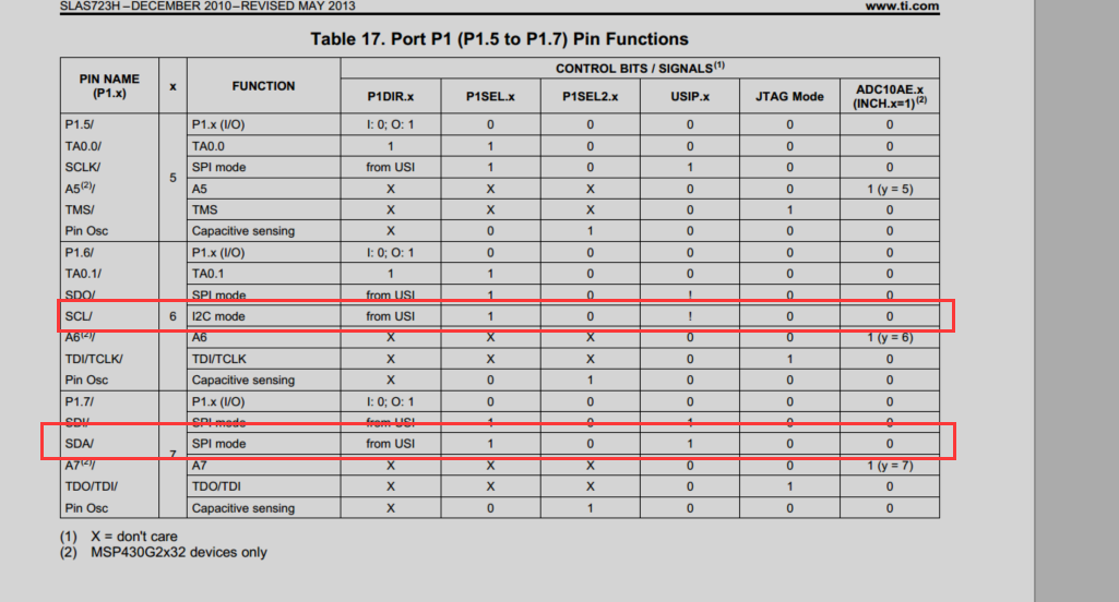
Should I configure the P1SEL and P1SEL2 registers?
I also find the MSP430x2xx Family User‘s Guide says that:
'On some I/O ports on the MSP430F261x and MSP430F2416/7/8/9, enabling the
pullup/pulldown resistor (PxREN = 1) while the module function is selected (PxSEL = 1) does
not disable the logic output driver. This combination is not recommended and may result in
unwanted current flow through the internal resistor. See the device-specific data sheet pin
schematics for more information. '
This passage doesn't mention the MSP430G2102, is this means MSP430G2102 can set PxSEL = 1 while enabled Pullups?
If there are pull-up registers outside, Can I disable the internal pull-up registers?
Thanks!
