This thread has been locked.

If you have a related question, please click the "Ask a related question" button in the top right corner. The newly created question will be automatically linked to this question.

MSP430F5528: EZ Fet Lite throwing a Exit: 44 Could not set device Vcc error

Part Number: MSP430F5528
Other Parts Discussed in Thread: MSP430G2553, MSP430-FLASHER, MSP-FET

We have implemented an EZFet Lite design and are running MSP Flasher v1.3.14 from Linux.  We are programming a G2553

When running the following command:

./MSP430Flasher -n MSP430G2553 -r [output.txt,MAIN]

We get the following output:

* -----/|-------------------------------------------------------------------- *-r

*     / |__                                                                   *

*    /_   /   MSP Flasher v1.3.14                                             *

*      | /                                                                    *

* -----|/-------------------------------------------------------------------- *

*

* Evaluating triggers...done

* Checking for available FET debuggers:

* Found USB FET @ ttyACM1 <- Selected

* Initializing interface @ ttyACM1...done

* Checking firmware compatibility:

* FET firmware is up to date.

* Reading FW version...done

* Setting VCC to 3000 mV...

# Exit: 44

# ERROR: Could not set device Vcc

* Powering down...done

* Disconnecting from device...

* ----------------------------------------------------------------------------

* ERROR on close: Could not set device Vcc

* ----------------------------------------------------------------------------

*/

Our board is at 3.3v rather than 3.0v.  We did find a note in the user guide saying the EZFet only supports 3.0v, but we are not sure of the ramifications or if we can spoof the software...

Is our problem hardware or the command string we are sending.  Ideas?

  • I'm assuming that the eZ-FET lite v1.10 release package is programmed? Are you able to test the eZ-FET lite HW design on Windows, with CCS, and/or using a TI EVM target board or LaunchPad? Can the G2553 target board be programmed with a LaunchPad eZ-FET or MSP-FET with MSP430-FLASHER? What connections are made between the FET and target?

    Regards,
    Ryan
  • Hi Ryan,

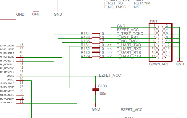
    Schematic to be sent offline.

    We can program the G2553 target with an external connection.

    We can program the 5528 offline with a MSPFET.

    The schematic I am sending is only the 5528 side right now.  He is sending the G2553 later.

    The 5528 is headless Linux only.  No Windows possible.

    He did flywire it to a EVM target board (MSP-TS430RGC64USB) and got an identical error message.

    I am thinking putting a scope on RST/TST and sending us waveforms?

    Note:  You will see some switch circuitry so he can program multiple MSP430's on his board (6 total), but he has bypassed it hardwiring directly to the G2553.

    Blake

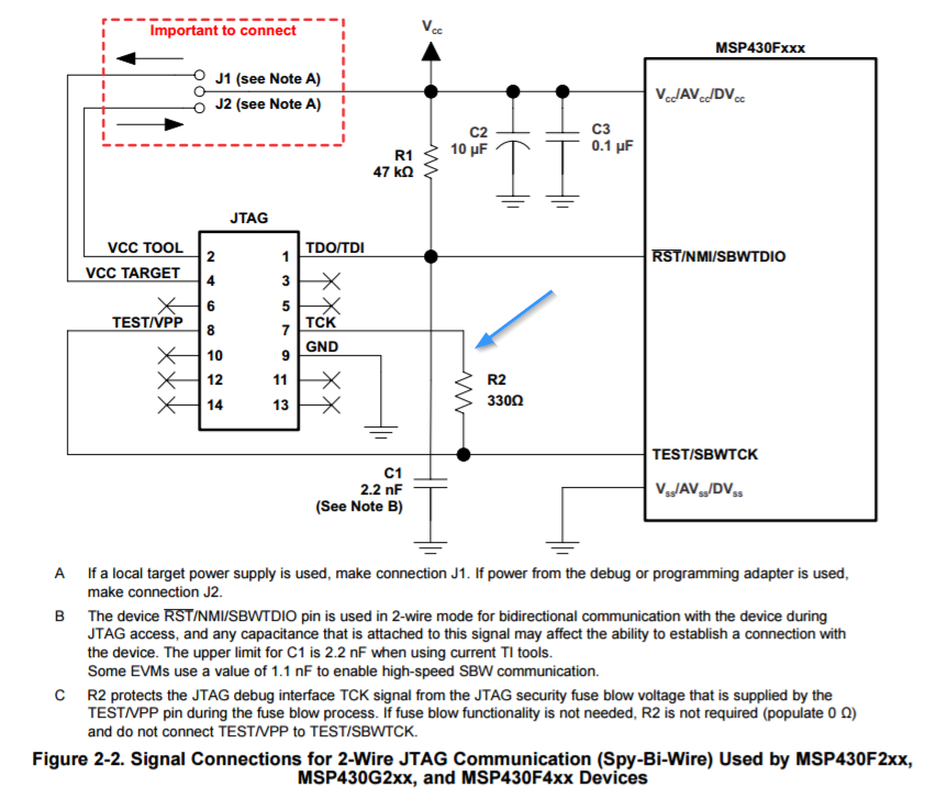
  • Hmmmm.... In reviewing the schematic, I notice he has only hooked up /RST and TST. He has not hooked up any of pins 9,11,13,15,17 which are the backchannel UART and the /TMSC. Could this interfere with the EZFET function?

    Blake
  • I notice this line is missing:

    but it doesn't seem to be explicitly called out on the ezfet-Lite:

  • Customer suggests that he has scope lines on SBWTDIO (high) and SBWTCK (Low) and that neither of them ever trigger... He has had triggering problems in the past with that scope (I have noticed). I may take my scope over if we run out of ideas.

    Blake
  • Did they follow the eZ-FET lite Production Test Spec document when programming the F5528, and did it pass? Backchannel UART, /TMSC, and the TCK connection are not required for eZ-FET lite programming functionality. Does the customer not use a TLV700xx LDO to drop the VBUS (5 V) down to 3.3 V? Are both voltages supplied during programming? Please describe the USB interface since a mini/micro-USB connection is not shown. The multiplexer setup is concerning as eZ-FET lite circuitry has only been tested with one direct target connection. Is only one target device populated and is it receiving power and GND from the FET?

    Regards,
    Ryan
  • Hi Ryan,

    From the Customer:

    1.  We did not follow the Production Test Spec when programming.  I do not have the application to run.  If it can be provided to me, I will run it. [Blake:  He can't find the executable]


    2.  No, we do not use the regulator to drop the voltage from the VBUS to 3.3V.  VBUS is supplied from the external host and the 3.3V is supplied by the onboard 3.3V supply.  The 3.3V is present before VBUS.  However, the micro seems to be running and responds to commands over the USB connection.


    3.  Both voltages are supplied during programming.


    4.  There is no connector, the devices are connected on the circuit board as this is intended to be deployed as part of the system, dedicated to programming the other MSP430s on the assembly.


    Some additional information from my morning testing...


    I ran MSPFlasher with my TI MSP-FET.  On the Linux system it indicated the FW was out of date and I went through the procedure to update the FW, at least three times.  Each attempt was unsuccessful.  I then restored the firmware with my version of CCS.  I then connected the TI MSP-FET to my Windows workstation.  As before, it indicated the FW was out of date.  However, this time the FW update succeeded on the first attempt.  I was then able to read the attached MSP430G2553 configuration.


    I next attached the TI MSP-FET  to the Linux based system.  When I ran the MSP430Flasher –i DETECT, it indicated the FW was outdated.  I bypassed the FW update and received the Exit: 44 as in every other case.


    The fact that I could successfully complete the task under Windows, but have been flagged as having outdated FW and the same exit condition I have received each time suggests there is a problem with the Linux files distributed with this package.  At least with the version of Ubuntu I am running on my test system.


    Maybe these additional observations will be helpful in identifying the problem.

  • Hi Blake,

    The eZ-FET lite Production Test Spec executable is not provided, the customer will have to build it using the Microsoft Visual C++ 2010 source project. I will see if the Tools team can provide us with a direct executable. Meanwhile, it is important that both the eZ-FET BSL and FW be programmed to the target MSP4320F5528 in order for it to operate correctly.

    Regards,
    Ryan
  • Thanks Ryan,

    The new BSL was the missing bit.

    Using Elprotronic software, and an MSP-FET, we were able to program the BSL and code into his chip on his board and the same code onto a TI target socket board for the F5529.

    So now we have a TI target socket board with the EZ-FET lite firmware on it that we can talk to using a windows PC (1.3.10) or a Linux laptop (1.3.14).  It is connected to the spi by wire of a 2553 launchpad.

    The target board  F5529 sees the G2553 under Windows (flasher version 1.3.10) but gives an error 16 under ubuntu linux (mspflasher version 1.3.14)

    His board, same firmware exits with an error code 16.  

    We'll troubleshoot from here and I'll post results in a week or so.

    No actions from your side.

    Thanks!

**Attention** This is a public forum