This thread has been locked.

If you have a related question, please click the "Ask a related question" button in the top right corner. The newly created question will be automatically linked to this question.

MSP-GANG: MSP-Gang programmer shows Error 23: MCU device init

Part Number: MSP-GANG
Other Parts Discussed in Thread: MSP430F6459

Customer feedback initially MSP-Gang programmer is able to program when running with small quantity. After 2 weeks of deployment, it shows Error 23: MCU device init. It is unable to perform programming...error message always show unable to init MCU.Customer used it to program MSP430F6459, connection through Vcc,Gnd Test and RST pin. Customer has performed a selftest on the device and found that RST signal on Cav 2 to 7 are having ERROR.The target MCU has R1(47K) and C1(1nF) at the RST pin of the target MCU on board.The programmer is already having ERROR on RST during selftest. The firmware version of the MSP-Gang is 01.02.08.00 . Please advice whether the MSP-Gang programmer is faulty. Thank you.

  • Hi Ng,

    Can you please attach the output file of the selftest? You can do this by clicking the link for "insert code, attach files and more..." on the bottom right when you are replying, then using the paperclip icon for "insert file".

    Regards,
    Katie

  • Hi Katie,

    Please refer to the attached file. Thank you.

    6562.MSP-GANG-SelTestReport.txt
    === MSP-GANG Self test results ( Thursday, October 19, 2017,  16:26:56 ) ===
    
    Adapter SN ------:  16060400 
    Hardware --------:  G430:  01.04
    Access key ------:  MSP-GANG Programmer 
    Silicon Number --:  66AF 1447 2600 0F00
    API Firmware ----:  MSP-Gang   A430:  01.02.08.00
    BOOT Firmware ---:  G430BOOT   B430:  01.00.02.00
    GUI Software ----:  MSP-Gang-GUI   G430:  01.02.08.00
    DLL Software ----:  MSP-Gang-DLL   D430:  01.02.08.00
    
    ================ Test results =============
    
    
    No.       name                   parameter       limits               result         status
    
    
      1: Data Bus   (ALL LOW)          0x0000   (0x0000  - 0x0000)  Result:  0x00     ... >>  OK   <<
      2: Data Bus   (ALL HIGH)         0x00FF   (0xFFFF  - 0xFFFF)  Result:  0xFFFF   ... >>  OK   <<
      3: Data Bus   (D-0 HI )          0x0001   (0x0101  - 0x0101)  Result:  0x0101   ... >>  OK   <<
      4: Data Bus   (D-1 HI )          0x0002   (0x0202  - 0x0202)  Result:  0x0202   ... >>  OK   <<
      5: Data Bus   (D-2 HI )          0x0004   (0x0404  - 0x0404)  Result:  0x0404   ... >>  OK   <<
      6: Data Bus   (D-3 HI )          0x0008   (0x0808  - 0x0808)  Result:  0x0808   ... >>  OK   <<
      7: Data Bus   (D-4 HI )          0x0010   (0x1010  - 0x1010)  Result:  0x1010   ... >>  OK   <<
      8: Data Bus   (D-5 HI )          0x0020   (0x2020  - 0x2020)  Result:  0x2020   ... >>  OK   <<
      9: Data Bus   (D-6 HI )          0x0040   (0x4040  - 0x4040)  Result:  0x4040   ... >>  OK   <<
     10: Data Bus   (D-7 HI )          0x0080   (0x8080  - 0x8080)  Result:  0x8080   ... >>  OK   <<
    
     11: Data-2 Bus  (ALL LOW)         0x0000   (0x0000  - 0x0000)  Result:  0x00     ... >>  OK   <<
     12: Data-2 Bus  (ALL HIGH)        0x00FF   (0xFFFF  - 0xFFFF)  Result:  0xFFFF   ... >>  OK   <<
     13: Data-2 Bus  (D2-0 HI )        0x0001   (0x0101  - 0x0101)  Result:  0x0101   ... >>  OK   <<
     14: Data-2 Bus  (D2-1 HI )        0x0002   (0x0202  - 0x0202)  Result:  0x0202   ... >>  OK   <<
     15: Data-2 Bus  (D2-2 HI )        0x0004   (0x0404  - 0x0404)  Result:  0x0404   ... >>  OK   <<
     16: Data-2 Bus  (D2-3 HI )        0x0008   (0x0808  - 0x0808)  Result:  0x0808   ... >>  OK   <<
     17: Data-2 Bus  (D2-4 HI )        0x0010   (0x1010  - 0x1010)  Result:  0x1010   ... >>  OK   <<
     18: Data-2 Bus  (D2-5 HI )        0x0020   (0x2020  - 0x2020)  Result:  0x2020   ... >>  OK   <<
     19: Data-2 Bus  (D2-6 HI )        0x0040   (0x4040  - 0x4040)  Result:  0x4040   ... >>  OK   <<
     20: Data-2 Bus  (D2-7 HI )        0x0080   (0x8080  - 0x8080)  Result:  0x8080   ... >>  OK   <<
    
     21: Vcc Target-1 (ALL OFF)         0.00 V  (  0.00 to   0.30)  Result:  0.02 V   ... >>  OK   <<
     22: Vcc Target-2 (ALL OFF)         0.00 V  (  0.00 to   0.30)  Result:  0.01 V   ... >>  OK   <<
     23: Vcc Target-3 (ALL OFF)         0.00 V  (  0.00 to   0.30)  Result:  0.01 V   ... >>  OK   <<
     24: Vcc Target-4 (ALL OFF)         0.00 V  (  0.00 to   0.30)  Result:  0.01 V   ... >>  OK   <<
     25: Vcc Target-5 (ALL OFF)         0.00 V  (  0.00 to   0.30)  Result:  0.01 V   ... >>  OK   <<
     26: Vcc Target-6 (ALL OFF)         0.00 V  (  0.00 to   0.30)  Result:  0.01 V   ... >>  OK   <<
     27: Vcc Target-7 (ALL OFF)         0.00 V  (  0.00 to   0.30)  Result:  0.01 V   ... >>  OK   <<
     28: Vcc Target-8 (ALL OFF)         0.00 V  (  0.00 to   0.30)  Result:  0.01 V   ... >>  OK   <<
    
     29: Translators VT (OFF)           0.00 V  (  0.00 to   0.50)  Result:  0.01 V   ... >>  OK   <<
     30: Translators VT (ON 1.8V)       1.80 V  (  1.60 to   2.00)  Result:  1.73 V   ... >>  OK   <<
     31: Translators VT (ON 2.7V)       2.70 V  (  2.50 to   2.90)  Result:  2.62 V   ... >>  OK   <<
     32: Translators VT (ON 3.6V)       3.60 V  (  3.40 to   3.80)  Result:  3.52 V   ... >>  OK   <<
    
     33: Vpp Voltage-in                10.00 V  (  8.00 to  12.00)  Result: 10.19 V   ... >>  OK   <<
     34: Vpp Voltage                    7.00 V  (  6.50 to   7.30)  Result:  6.89 V   ... >>  OK   <<
     35: Internal Vcc-3.3V              3.30 V  (  3.20 to   3.40)  Result:  3.31 V   ... >>  OK   <<
    
     36: Vcc Target-1 (ALL ON 1.8V)     1.80 V  (  1.60 to   2.00)  Result:  1.81 V   ... >>  OK   <<
     37: Vcc Target-2 (ALL ON 1.8V)     1.80 V  (  1.60 to   2.00)  Result:  1.79 V   ... >>  OK   <<
     38: Vcc Target-3 (ALL ON 1.8V)     1.80 V  (  1.60 to   2.00)  Result:  1.80 V   ... >>  OK   <<
     39: Vcc Target-4 (ALL ON 1.8V)     1.80 V  (  1.60 to   2.00)  Result:  1.81 V   ... >>  OK   <<
     40: Vcc Target-5 (ALL ON 1.8V)     1.80 V  (  1.60 to   2.00)  Result:  1.80 V   ... >>  OK   <<
     41: Vcc Target-6 (ALL ON 1.8V)     1.80 V  (  1.60 to   2.00)  Result:  1.81 V   ... >>  OK   <<
     42: Vcc Target-7 (ALL ON 1.8V)     1.80 V  (  1.60 to   2.00)  Result:  1.79 V   ... >>  OK   <<
     43: Vcc Target-8 (ALL ON 1.8V)     1.80 V  (  1.60 to   2.00)  Result:  1.80 V   ... >>  OK   <<
     44: Vcc Target-1 (ALL ON 2.7V)     2.70 V  (  2.50 to   2.90)  Result:  2.70 V   ... >>  OK   <<
     45: Vcc Target-2 (ALL ON 2.7V)     2.70 V  (  2.50 to   2.90)  Result:  2.67 V   ... >>  OK   <<
     46: Vcc Target-3 (ALL ON 2.7V)     2.70 V  (  2.50 to   2.90)  Result:  2.70 V   ... >>  OK   <<
     47: Vcc Target-4 (ALL ON 2.7V)     2.70 V  (  2.50 to   2.90)  Result:  2.71 V   ... >>  OK   <<
     48: Vcc Target-5 (ALL ON 2.7V)     2.70 V  (  2.50 to   2.90)  Result:  2.70 V   ... >>  OK   <<
     49: Vcc Target-6 (ALL ON 2.7V)     2.70 V  (  2.50 to   2.90)  Result:  2.71 V   ... >>  OK   <<
     50: Vcc Target-7 (ALL ON 2.7V)     2.70 V  (  2.50 to   2.90)  Result:  2.69 V   ... >>  OK   <<
     51: Vcc Target-8 (ALL ON 2.7V)     2.70 V  (  2.50 to   2.90)  Result:  2.69 V   ... >>  OK   <<
     52: Vcc Target-1 (ALL ON 3.6V)     3.60 V  (  3.40 to   3.80)  Result:  3.59 V   ... >>  OK   <<
     53: Vcc Target-2 (ALL ON 3.6V)     3.60 V  (  3.40 to   3.80)  Result:  3.57 V   ... >>  OK   <<
     54: Vcc Target-3 (ALL ON 3.6V)     3.60 V  (  3.40 to   3.80)  Result:  3.60 V   ... >>  OK   <<
     55: Vcc Target-4 (ALL ON 3.6V)     3.60 V  (  3.40 to   3.80)  Result:  3.61 V   ... >>  OK   <<
     56: Vcc Target-5 (ALL ON 3.6V)     3.60 V  (  3.40 to   3.80)  Result:  3.60 V   ... >>  OK   <<
     57: Vcc Target-6 (ALL ON 3.6V)     3.60 V  (  3.40 to   3.80)  Result:  3.61 V   ... >>  OK   <<
     58: Vcc Target-7 (ALL ON 3.6V)     3.60 V  (  3.40 to   3.80)  Result:  3.59 V   ... >>  OK   <<
     59: Vcc Target-8 (ALL ON 3.6V)     3.60 V  (  3.40 to   3.80)  Result:  3.59 V   ... >>  OK   <<
    
     60: Vcc discharge (100ms)Target-1  3.60 V  (  1.00 to   2.70)  Result:  1.13 V   ... >>  OK   <<
     61: Vcc discharge (100ms)Target-2  3.60 V  (  1.00 to   2.70)  Result:  1.12 V   ... >>  OK   <<
     62: Vcc discharge (100ms)Target-3  3.60 V  (  1.00 to   2.70)  Result:  1.14 V   ... >>  OK   <<
     63: Vcc discharge (100ms)Target-4  3.60 V  (  1.00 to   2.70)  Result:  1.15 V   ... >>  OK   <<
     64: Vcc discharge (100ms)Target-5  3.60 V  (  1.00 to   2.70)  Result:  1.13 V   ... >>  OK   <<
     65: Vcc discharge (100ms)Target-6  3.60 V  (  1.00 to   2.70)  Result:  1.11 V   ... >>  OK   <<
     66: Vcc discharge (100ms)Target-7  3.60 V  (  1.00 to   2.70)  Result:  1.16 V   ... >>  OK   <<
     67: Vcc discharge (100ms)Target-8  3.60 V  (  1.00 to   2.70)  Result:  1.11 V   ... >>  OK   <<
    
     68: Vcc Target-1 ( #1 ON )         0.00 V  (  3.10 to   3.50)  Result:  3.29 V   ... >>  OK   <<
     69: Vcc Target-2 ( #1 ON )         0.00 V  (  0.00 to   0.50)  Result:  0.16 V   ... >>  OK   <<
     70: Vcc Target-3 ( #1 ON )         0.00 V  (  0.00 to   0.50)  Result:  0.15 V   ... >>  OK   <<
     71: Vcc Target-4 ( #1 ON )         0.00 V  (  0.00 to   0.50)  Result:  0.15 V   ... >>  OK   <<
     72: Vcc Target-5 ( #1 ON )         0.00 V  (  0.00 to   0.50)  Result:  0.15 V   ... >>  OK   <<
     73: Vcc Target-6 ( #1 ON )         0.00 V  (  0.00 to   0.50)  Result:  0.15 V   ... >>  OK   <<
     74: Vcc Target-7 ( #1 ON )         0.00 V  (  0.00 to   0.50)  Result:  0.15 V   ... >>  OK   <<
     75: Vcc Target-8 ( #1 ON )         3.30 V  (  0.00 to   0.50)  Result:  0.15 V   ... >>  OK   <<
     76: Vcc Target-1 ( #2 ON )         0.00 V  (  0.00 to   0.50)  Result:  0.16 V   ... >>  OK   <<
     77: Vcc Target-2 ( #2 ON )         0.00 V  (  3.10 to   3.50)  Result:  3.27 V   ... >>  OK   <<
     78: Vcc Target-3 ( #2 ON )         0.00 V  (  0.00 to   0.50)  Result:  0.16 V   ... >>  OK   <<
     79: Vcc Target-4 ( #2 ON )         0.00 V  (  0.00 to   0.50)  Result:  0.15 V   ... >>  OK   <<
     80: Vcc Target-5 ( #2 ON )         0.00 V  (  0.00 to   0.50)  Result:  0.15 V   ... >>  OK   <<
     81: Vcc Target-6 ( #2 ON )         0.00 V  (  0.00 to   0.50)  Result:  0.15 V   ... >>  OK   <<
     82: Vcc Target-7 ( #2 ON )         0.00 V  (  0.00 to   0.50)  Result:  0.15 V   ... >>  OK   <<
     83: Vcc Target-8 ( #2 ON )         3.30 V  (  0.00 to   0.50)  Result:  0.15 V   ... >>  OK   <<
     84: Vcc Target-1 ( #3 ON )         0.00 V  (  0.00 to   0.50)  Result:  0.16 V   ... >>  OK   <<
     85: Vcc Target-2 ( #3 ON )         0.00 V  (  0.00 to   0.50)  Result:  0.16 V   ... >>  OK   <<
     86: Vcc Target-3 ( #3 ON )         0.00 V  (  3.10 to   3.50)  Result:  3.30 V   ... >>  OK   <<
     87: Vcc Target-4 ( #3 ON )         0.00 V  (  0.00 to   0.50)  Result:  0.16 V   ... >>  OK   <<
     88: Vcc Target-5 ( #3 ON )         0.00 V  (  0.00 to   0.50)  Result:  0.15 V   ... >>  OK   <<
     89: Vcc Target-6 ( #3 ON )         0.00 V  (  0.00 to   0.50)  Result:  0.15 V   ... >>  OK   <<
     90: Vcc Target-7 ( #3 ON )         0.00 V  (  0.00 to   0.50)  Result:  0.15 V   ... >>  OK   <<
     91: Vcc Target-8 ( #3 ON )         3.30 V  (  0.00 to   0.50)  Result:  0.15 V   ... >>  OK   <<
     92: Vcc Target-1 ( #4 ON )         0.00 V  (  0.00 to   0.50)  Result:  0.16 V   ... >>  OK   <<
     93: Vcc Target-2 ( #4 ON )         0.00 V  (  0.00 to   0.50)  Result:  0.15 V   ... >>  OK   <<
     94: Vcc Target-3 ( #4 ON )         0.00 V  (  0.00 to   0.50)  Result:  0.15 V   ... >>  OK   <<
     95: Vcc Target-4 ( #4 ON )         0.00 V  (  3.10 to   3.50)  Result:  3.31 V   ... >>  OK   <<
     96: Vcc Target-5 ( #4 ON )         0.00 V  (  0.00 to   0.50)  Result:  0.16 V   ... >>  OK   <<
     97: Vcc Target-6 ( #4 ON )         0.00 V  (  0.00 to   0.50)  Result:  0.15 V   ... >>  OK   <<
     98: Vcc Target-7 ( #4 ON )         0.00 V  (  0.00 to   0.50)  Result:  0.15 V   ... >>  OK   <<
     99: Vcc Target-8 ( #4 ON )         3.30 V  (  0.00 to   0.50)  Result:  0.15 V   ... >>  OK   <<
    100: Vcc Target-1 ( #5 ON )         0.00 V  (  0.00 to   0.50)  Result:  0.16 V   ... >>  OK   <<
    101: Vcc Target-2 ( #5 ON )         0.00 V  (  0.00 to   0.50)  Result:  0.15 V   ... >>  OK   <<
    102: Vcc Target-3 ( #5 ON )         0.00 V  (  0.00 to   0.50)  Result:  0.15 V   ... >>  OK   <<
    103: Vcc Target-4 ( #5 ON )         0.00 V  (  0.00 to   0.50)  Result:  0.15 V   ... >>  OK   <<
    104: Vcc Target-5 ( #5 ON )         0.00 V  (  3.10 to   3.50)  Result:  3.29 V   ... >>  OK   <<
    105: Vcc Target-6 ( #5 ON )         0.00 V  (  0.00 to   0.50)  Result:  0.16 V   ... >>  OK   <<
    106: Vcc Target-7 ( #5 ON )         0.00 V  (  0.00 to   0.50)  Result:  0.15 V   ... >>  OK   <<
    107: Vcc Target-8 ( #5 ON )         3.30 V  (  0.00 to   0.50)  Result:  0.15 V   ... >>  OK   <<
    108: Vcc Target-1 ( #6 ON )         0.00 V  (  0.00 to   0.50)  Result:  0.16 V   ... >>  OK   <<
    109: Vcc Target-2 ( #6 ON )         0.00 V  (  0.00 to   0.50)  Result:  0.15 V   ... >>  OK   <<
    110: Vcc Target-3 ( #6 ON )         0.00 V  (  0.00 to   0.50)  Result:  0.15 V   ... >>  OK   <<
    111: Vcc Target-4 ( #6 ON )         0.00 V  (  0.00 to   0.50)  Result:  0.15 V   ... >>  OK   <<
    112: Vcc Target-5 ( #6 ON )         0.00 V  (  0.00 to   0.50)  Result:  0.15 V   ... >>  OK   <<
    113: Vcc Target-6 ( #6 ON )         0.00 V  (  3.10 to   3.50)  Result:  3.31 V   ... >>  OK   <<
    114: Vcc Target-7 ( #6 ON )         0.00 V  (  0.00 to   0.50)  Result:  0.16 V   ... >>  OK   <<
    115: Vcc Target-8 ( #6 ON )         3.30 V  (  0.00 to   0.50)  Result:  0.15 V   ... >>  OK   <<
    116: Vcc Target-1 ( #7 ON )         0.00 V  (  0.00 to   0.50)  Result:  0.16 V   ... >>  OK   <<
    117: Vcc Target-2 ( #7 ON )         0.00 V  (  0.00 to   0.50)  Result:  0.15 V   ... >>  OK   <<
    118: Vcc Target-3 ( #7 ON )         0.00 V  (  0.00 to   0.50)  Result:  0.15 V   ... >>  OK   <<
    119: Vcc Target-4 ( #7 ON )         0.00 V  (  0.00 to   0.50)  Result:  0.15 V   ... >>  OK   <<
    120: Vcc Target-5 ( #7 ON )         0.00 V  (  0.00 to   0.50)  Result:  0.15 V   ... >>  OK   <<
    121: Vcc Target-6 ( #7 ON )         0.00 V  (  0.00 to   0.50)  Result:  0.15 V   ... >>  OK   <<
    122: Vcc Target-7 ( #7 ON )         0.00 V  (  3.10 to   3.50)  Result:  3.29 V   ... >>  OK   <<
    123: Vcc Target-8 ( #7 ON )         3.30 V  (  0.00 to   0.50)  Result:  0.16 V   ... >>  OK   <<
    124: Vcc Target-1 ( #8 ON )         0.00 V  (  0.00 to   0.50)  Result:  0.16 V   ... >>  OK   <<
    125: Vcc Target-2 ( #8 ON )         0.00 V  (  0.00 to   0.50)  Result:  0.15 V   ... >>  OK   <<
    126: Vcc Target-3 ( #8 ON )         0.00 V  (  0.00 to   0.50)  Result:  0.15 V   ... >>  OK   <<
    127: Vcc Target-4 ( #8 ON )         0.00 V  (  0.00 to   0.50)  Result:  0.15 V   ... >>  OK   <<
    128: Vcc Target-5 ( #8 ON )         0.00 V  (  0.00 to   0.50)  Result:  0.15 V   ... >>  OK   <<
    129: Vcc Target-6 ( #8 ON )         0.00 V  (  0.00 to   0.50)  Result:  0.15 V   ... >>  OK   <<
    130: Vcc Target-7 ( #8 ON )         0.00 V  (  0.00 to   0.50)  Result:  0.15 V   ... >>  OK   <<
    131: Vcc Target-8 ( #8 ON )         3.30 V  (  3.10 to   3.50)  Result:  3.29 V   ... >>  OK   <<
    
    132: SD Power OFF                  0x0000   (0x0000  - 0x0000)  Result:  0x00     ... >>  OK   <<
    133: SD Power ON                   0x0001   (0x0001  - 0x0001)  Result:  0x01     ... >>  OK   <<
    134: SD Discharge -  delay 2ms     0x0010   (0x0001  - 0x0001)  Result:  0x01     ... >>  OK   <<
    135: SD Discharge -  delay 50ms    0x0010   (0x0000  - 0x0000)  Result:  0x00     ... >>  OK   <<
    
    136: BSL RX bus (#1 HIGH)          0x0001   (0x0001  - 0x0001)  Result:  0x00     ... >> ERROR <<
    137: BSL RX bus (#2 HIGH)          0x0002   (0x0002  - 0x0002)  Result:  0x00     ... >> ERROR <<
    138: BSL RX bus (#3 HIGH)          0x0004   (0x0004  - 0x0004)  Result:  0x00     ... >> ERROR <<
    139: BSL RX bus (#4 HIGH)          0x0008   (0x0008  - 0x0008)  Result:  0x00     ... >> ERROR <<
    140: BSL RX bus (#5 HIGH)          0x0010   (0x0010  - 0x0010)  Result:  0x00     ... >> ERROR <<
    141: BSL RX bus (#6 HIGH)          0x0020   (0x0020  - 0x0020)  Result:  0x00     ... >> ERROR <<
    142: BSL RX bus (#7 HIGH)          0x0040   (0x0040  - 0x0040)  Result:  0x40     ... >>  OK   <<
    143: BSL RX bus (#8 HIGH)          0x0080   (0x0080  - 0x0080)  Result:  0x00     ... >> ERROR <<
    
    144: BSL TX bus (#1 HIGH)          0x0001   (0x0001  - 0x0001)  Result:  0x00     ... >> ERROR <<
    145: BSL TX bus (#2 HIGH)          0x0002   (0x0002  - 0x0002)  Result:  0x00     ... >> ERROR <<
    146: BSL TX bus (#3 HIGH)          0x0004   (0x0004  - 0x0004)  Result:  0x00     ... >> ERROR <<
    147: BSL TX bus (#4 HIGH)          0x0008   (0x0008  - 0x0008)  Result:  0x00     ... >> ERROR <<
    148: BSL TX bus (#5 HIGH)          0x0010   (0x0010  - 0x0010)  Result:  0x00     ... >> ERROR <<
    149: BSL TX bus (#6 HIGH)          0x0020   (0x0020  - 0x0020)  Result:  0x00     ... >> ERROR <<
    150: BSL TX bus (#7 HIGH)          0x0040   (0x0040  - 0x0040)  Result:  0x40     ... >>  OK   <<
    151: BSL TX bus (#8 HIGH)          0x0080   (0x0080  - 0x0080)  Result:  0x00     ... >> ERROR <<
    
    152: TDI bus  (#1 HIGH)            0x0001   (0x0001  - 0x0001)  Result:  0x01     ... >>  OK   <<
    153: TDI bus  (#2 HIGH)            0x0002   (0x0002  - 0x0002)  Result:  0x02     ... >>  OK   <<
    154: TDI bus  (#3 HIGH)            0x0004   (0x0004  - 0x0004)  Result:  0x04     ... >>  OK   <<
    155: TDI bus  (#4 HIGH)            0x0008   (0x0008  - 0x0008)  Result:  0x08     ... >>  OK   <<
    156: TDI bus  (#5 HIGH)            0x0010   (0x0010  - 0x0010)  Result:  0x10     ... >>  OK   <<
    157: TDI bus  (#6 HIGH)            0x0020   (0x0020  - 0x0020)  Result:  0x20     ... >>  OK   <<
    158: TDI bus  (#7 HIGH)            0x0040   (0x0040  - 0x0040)  Result:  0x40     ... >>  OK   <<
    159: TDI bus  (#8 HIGH)            0x0080   (0x0080  - 0x0080)  Result:  0x80     ... >>  OK   <<
    
    160: TDOI Tx-bus (#1 HIGH)         0x0001   (0x0001  - 0x0001)  Result:  0x01     ... >>  OK   <<
    161: TDOI Tx-bus (#2 HIGH)         0x0002   (0x0002  - 0x0002)  Result:  0x02     ... >>  OK   <<
    162: TDOI Tx-bus (#3 HIGH)         0x0004   (0x0004  - 0x0004)  Result:  0x04     ... >>  OK   <<
    163: TDOI Tx-bus (#4 HIGH)         0x0008   (0x0008  - 0x0008)  Result:  0x08     ... >>  OK   <<
    164: TDOI Tx-bus (#5 HIGH)         0x0010   (0x0010  - 0x0010)  Result:  0x10     ... >>  OK   <<
    165: TDOI Tx-bus (#6 HIGH)         0x0020   (0x0020  - 0x0020)  Result:  0x20     ... >>  OK   <<
    166: TDOI Tx-bus (#7 HIGH)         0x0040   (0x0040  - 0x0040)  Result:  0x40     ... >>  OK   <<
    167: TDOI Tx-bus (#8 HIGH)         0x0080   (0x0080  - 0x0080)  Result:  0x80     ... >>  OK   <<
    
    168: TDOI Tx-Rx (#1 HIGH)          0x0001   (0x0001  - 0x0001)  Result:  0x01     ... >>  OK   <<
    169: TDOI Tx-Rx (#2 HIGH)          0x0002   (0x0002  - 0x0002)  Result:  0x02     ... >>  OK   <<
    170: TDOI Tx-Rx (#3 HIGH)          0x0004   (0x0004  - 0x0004)  Result:  0x04     ... >>  OK   <<
    171: TDOI Tx-Rx (#4 HIGH)          0x0008   (0x0008  - 0x0008)  Result:  0x08     ... >>  OK   <<
    172: TDOI Tx-Rx (#5 HIGH)          0x0010   (0x0010  - 0x0010)  Result:  0x10     ... >>  OK   <<
    173: TDOI Tx-Rx (#6 HIGH)          0x0020   (0x0020  - 0x0020)  Result:  0x20     ... >>  OK   <<
    174: TDOI Tx-Rx (#7 HIGH)          0x0040   (0x0040  - 0x0040)  Result:  0x40     ... >>  OK   <<
    175: TDOI Tx-Rx (#8 HIGH)          0x0080   (0x0080  - 0x0080)  Result:  0x80     ... >>  OK   <<
    
    176: TDOI Rx-bus (#1 HIGH)         0x0001   (0x0001  - 0x0001)  Result:  0x01     ... >>  OK   <<
    177: TDOI Rx-bus (#2 HIGH)         0x0002   (0x0002  - 0x0002)  Result:  0x02     ... >>  OK   <<
    178: TDOI Rx-bus (#3 HIGH)         0x0004   (0x0004  - 0x0004)  Result:  0x04     ... >>  OK   <<
    179: TDOI Rx-bus (#4 HIGH)         0x0008   (0x0008  - 0x0008)  Result:  0x08     ... >>  OK   <<
    180: TDOI Rx-bus (#5 HIGH)         0x0010   (0x0010  - 0x0010)  Result:  0x10     ... >>  OK   <<
    181: TDOI Rx-bus (#6 HIGH)         0x0020   (0x0020  - 0x0020)  Result:  0x20     ... >>  OK   <<
    182: TDOI Rx-bus (#7 HIGH)         0x0040   (0x0040  - 0x0040)  Result:  0x40     ... >>  OK   <<
    183: TDOI Rx-bus (#84 HIGH)        0x0080   (0x0080  - 0x0080)  Result:  0x80     ... >>  OK   <<
    
    184: TMS bus (All HIGH)            0x00FF   (0x00FF  - 0x00FF)  Result:  0xFF     ... >>  OK   <<
    185: TMS bus (All LOW)             0x0000   (0x0000  - 0x0000)  Result:  0x00     ... >>  OK   <<
    
    186: TMS bus (#1 HIGH)             0x0001   (0x0001  - 0x0001)  Result:  0x01     ... >>  OK   <<
    187: TMS bus (#2 HIGH)             0x0002   (0x0002  - 0x0002)  Result:  0x02     ... >>  OK   <<
    188: TMS bus (#3 HIGH)             0x0004   (0x0004  - 0x0004)  Result:  0x04     ... >>  OK   <<
    189: TMS bus (#4 HIGH)             0x0008   (0x0008  - 0x0008)  Result:  0x08     ... >>  OK   <<
    190: TMS bus (#5 HIGH)             0x0010   (0x0010  - 0x0010)  Result:  0x10     ... >>  OK   <<
    191: TMS bus (#6 HIGH)             0x0020   (0x0020  - 0x0020)  Result:  0x20     ... >>  OK   <<
    192: TMS bus (#7 HIGH)             0x0040   (0x0040  - 0x0040)  Result:  0x40     ... >>  OK   <<
    193: TMS bus (#8 HIGH)             0x0080   (0x0080  - 0x0080)  Result:  0x80     ... >>  OK   <<
    
    194: RST bus (All HIGH)            0x00FF   (0x00FF  - 0x00FF)  Result:  0xFF     ... >>  OK   <<
    195: RST bus (All LOW)             0x0000   (0x0000  - 0x0000)  Result:  0x00     ... >>  OK   <<
    
    196: RST bus (#1 HIGH)             0x0001   (0x0001  - 0x0001)  Result:  0x00     ... >> ERROR <<
    197: RST bus (#2 HIGH)             0x0002   (0x0002  - 0x0002)  Result:  0x00     ... >> ERROR <<
    198: RST bus (#3 HIGH)             0x0004   (0x0004  - 0x0004)  Result:  0x00     ... >> ERROR <<
    199: RST bus (#4 HIGH)             0x0008   (0x0008  - 0x0008)  Result:  0x00     ... >> ERROR <<
    200: RST bus (#5 HIGH)             0x0010   (0x0010  - 0x0010)  Result:  0x00     ... >> ERROR <<
    201: RST bus (#6 HIGH)             0x0020   (0x0020  - 0x0020)  Result:  0x00     ... >> ERROR <<
    202: RST bus (#7 HIGH)             0x0040   (0x0040  - 0x0040)  Result:  0x00     ... >> ERROR <<
    203: RST bus (#8 HIGH)             0x0080   (0x0080  - 0x0080)  Result:  0x00     ... >> ERROR <<
    
    204: Keys buffer (All pull-up)     0x001F   (0x001F  - 0x001F)  Result:  0x1F     ... >>  OK   <<
    
    205: Access to LCD RAM (0xAA)      0x00AA   (0x00AA  - 0x00AA)  Result:  0xAA     ... >>  OK   <<
    206: Access to LCD RAM (0x99)      0x0099   (0x0099  - 0x0099)  Result:  0x99     ... >>  OK   <<
    
    207: Image Flash Access (get ID)   0x0002   (0x0001  - 0x0003)  Result:  0x03     ... >>  OK   <<
    
    208: TDI Fuse keys (#1 ON)         0x0001   (0x0001  - 0x0001)  Result:  0x01     ... >>  OK   <<
    209: TDI Fuse keys (#2 ON)         0x0002   (0x0002  - 0x0002)  Result:  0x02     ... >>  OK   <<
    210: TDI Fuse keys (#3 ON)         0x0004   (0x0004  - 0x0004)  Result:  0x04     ... >>  OK   <<
    211: TDI Fuse keys (#4 ON)         0x0008   (0x0008  - 0x0008)  Result:  0x08     ... >>  OK   <<
    212: TDI Fuse keys (#5 ON)         0x0010   (0x0010  - 0x0010)  Result:  0x10     ... >>  OK   <<
    213: TDI Fuse keys (#6 ON)         0x0020   (0x0020  - 0x0020)  Result:  0x20     ... >>  OK   <<
    214: TDI Fuse keys (#7 ON)         0x0040   (0x0040  - 0x0040)  Result:  0x40     ... >>  OK   <<
    215: TDI Fuse keys (#8 ON)         0x0080   (0x0080  - 0x0080)  Result:  0x80     ... >>  OK   <<
    
    216: TEST Fuse keys (All OFF )      0.00    (  0.00 to   0.30)  Result:  0.00     ... >>  OK   <<
    217: TEST Fuse keys (#1 ON)         1.00    (  0.80 to   3.00)  Result:  1.93     ... >>  OK   <<
    218: TEST Fuse keys (#2 ON)         2.00    (  0.80 to   3.00)  Result:  2.30     ... >>  OK   <<
    219: TEST Fuse keys (#3 ON)         3.00    (  0.80 to   3.00)  Result:  2.38     ... >>  OK   <<
    220: TEST Fuse keys (#4 ON)         4.00    (  0.80 to   3.00)  Result:  2.10     ... >>  OK   <<
    221: TEST Fuse keys (#5 ON)         5.00    (  0.80 to   3.00)  Result:  2.10     ... >>  OK   <<
    222: TEST Fuse keys (#6 ON)         6.00    (  0.80 to   3.00)  Result:  2.10     ... >>  OK   <<
    223: TEST Fuse keys (#7 ON)         7.00    (  0.80 to   3.00)  Result:  2.10     ... >>  OK   <<
    224: TEST Fuse keys (#8 ON)         8.00    (  0.80 to   3.00)  Result:  2.10     ... >>  OK   <<
    
    ============== Finished =================================
    *  Test failed!!  22 error(s).
    =========================================================
    

    Regards,

    Gim Huat

  • Hi Gim Huat,

    This is helpful - thank you for providing the report. Based on the report, we have some questions about what sequence is used in your programming set up.

    1. Are the target devices being powered externally, or from the MSP-GANG? (e.g. is there a battery already on the targets or a power supply on the targets, rather than the targets just being powered by the MSP-GANG)?
    2. If the targets do have an external power supply, are they already powered before the MSP-GANG is connected to them?

    Regards,
    Katie
  •  Hi Katie,

    Please refer to customer reply as below.

    1. Are the target devices being powered externally, or from the MSP-GANG? (e.g. is there a battery already on the targets or a power supply on the targets, rather than the targets just being powered by the MSP-GANG)?

    --> We are using external power supply.

    2. If the targets do have an external power supply, are they already powered before the MSP-GANG is connected to them?

    --> No. JTAG connected.. Follow by power on.

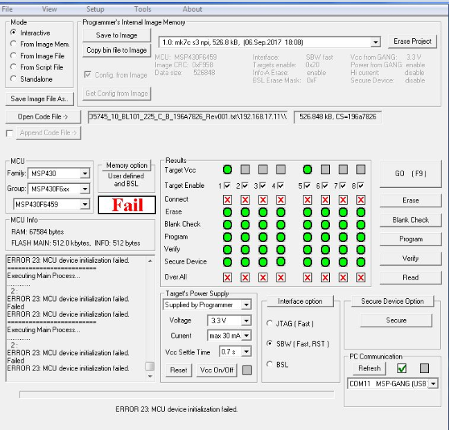
    Please refer to attached screen shot of customer setup.

    Under the Target's power supply, customer has selected "Supplied by Programmer"

    Is this correct?

    Regards,

    Gim Huat

  • Hi Gim Huat,

    If there is an external power supply being attached to the target device boards and providing power to them, then the MSP-GANG should not be set to Supplied by programmer - this will cause a voltage conflict between the programmer and the device. You should instead use the dropdown to select one of the external power options.

    Additionally, can you share a schematic snippet showing the MSP430 device connections to the MSP-GANG JTAG/SBW header? The reason I ask is that there should be a different Vcc connection depending on internal or external power option. If you use power supplied from the GANG to the target MSP, then the target Vcc should be connected to MSP-GANG pin 2. But if as you've described the target MSP has an external power supply, then the target Vcc should only be connected to MSP-GANG pin 4. This is so that the MSP-GANG can adjust its programming signals to follow the voltage being provided externally to the target and thereby avoid voltage conflicts. You can find a diagram with recommended programming connections in the hardware tools user's guide www.ti.com/lit/pdf/slau278
     
    Regards,
    Katie

  • 4370.schematic.pdfHi Katie,

    Please refer to the attached schematics. Customer say he is connecting to J1 by setting the Jumper JP-1a to pin 2 and 3. If set to Pin2 and Pin3 , it is using external source.

    Regards,

    Gim Huat

  • Hi Gim Huat,

    This brings some more confusion - you describe that pin 2 and 3 are connected on the jumper for external power. But in the GUI image that you showed it is set for internal MSP-GANG power. That conflict is an issue and in fact I would think that the programming would give an error in this case. Can they confirm what is a working setup of software and hardware on an MSP-GANG that hasn't been having these recent issues - screenshot of GUI + the jumper position and Vcc voltage supplied externally?

    Regards,
    Katie

  • Hi Katie,

    Customer reply as below:
    The design for this test board have 2 options;

    Option 1- Jumper JP1 set to 2 and 3
    VCC-1 is connected to Programmer Supply, it use Programmer Supply to trigger the Relay, this Relay will close circuit and supply BL +3V3 to target.

    Option 2 – Jumper JP1 set to 1 and 2.
    The target are supply by Programmer

    Regards,
    Gim Huat
  • Hi Gim Huat,

    Is the relay not shown in the diagram - I just see an overcurrent protection device on JP1 pin 2 and a diode, but nothing that connects to VCC-1 when you have JP1 in the 2 and 3 position.

    If they truly have VCC-1 connected instead of Vext-1 connected when they use external supply, and have the GUI set as shown above, this is a violation of the usage conditions of the MSP-GANG. If you are externally powering the device, VCC-1 must not be connected, Vext-1 must be connected, and the GUI must be set for using external supply instead of internal. Otherwise you can have voltage conflicts.

    Another question: when they ran the self-test - was this with the programming jig shown in the schematic attached to the GANG? If so, can you also run the self-test without anything attached to the MSP-GANG - do you see the same results?

    Regards,
    Katie
  • mspgang.docxHi Katie,

    Please refer below for the schematics.

    Customer reply the self test are run without anything attached to it..

  • Hi Gim Huat,

    Thanks for the additional notes. However, as I mentioned in my above post, this just confirms they are violating the usage of the MSP-GANG. They could be damaging the device or damaging MSP-GANG programmer. They need to change their programming setup.

    The issue is that they are having MSP-GANG set to supply the voltage from the programmer, but then really are supplying the voltage from an external source (whenever they use the jumper on position 2+3). In this case, because of the MSP-GANG setting in the GUI to be supplying voltage, it is not expecting to see any potentially different voltage on other lines, but it could be slightly different because it is a different external supply. If they use external supply, they will have to change their setup so that they can have the external supply turned on but have the MSP-GANG GUI set for external supply - that is the only accepted usage with external power supply. What they are doing currently is not recommended.

    Additionally, with their schematic Vext-1 will still be connected in addition to VCC-1 even if they use MSP-GANG to supply power with JP-1 in position 1+2 - this is also a violation of the MSP-GANG recommended programming connections. You must have Vext-1 disconnected if you are programming with MSP-GANG supplying the power. Something will have to change in their programming setup to alter this programming jig interface or the cabling connections to the MSP device so that VCC-1 and Vext-1 are never connected at the same time for the MSP-GANG supplying power case.

    Regards,

    Katie

  • Hi Katie,

    Noted. I will inform to customer.
    Thank you so much for the help.

    Regards,
    Gim Huat

**Attention** This is a public forum