This thread has been locked.

If you have a related question, please click the "Ask a related question" button in the top right corner. The newly created question will be automatically linked to this question.

MSP430F2471: MSP430F2471

Part Number: MSP430F2471

I had interfaced a humidity sensor by going through the datasheet, user guide and application report.  I have some issues related to i2c.

ACKNOWLEDGMENT NOT GIVEN FROM THE SENSOR

Issues

  1. Acknowledgement not given from the sensor after writing the start, write address byte of the slave, stop.
  2. Is the pulse width of the SCL is correct?

Things I have done to generate clock and data:

***************************************************

 UCB1BR0 = 12;                                           // fSCL =SMCLK/12 = ~100kHz

 UCB1BR1 = 0;

 UCB1I2CSA = 0x51;                                  // default  slave address (0x28 )given in the sensor data sheet

 *******Continuous loop for Start,and Stop and Write address of Slave *****************

 while(1)

{

UCB1CTL1 |= UCTXSTT;                       // I2C start condition

UCB1CTL1 |= UCTXSTP;                      // Generate I2C stop condition

}

Other than above I have set necessary configurations for USCI module.

My question as per I2C protocol and data sheet gave the Start sequence, 7-bit slave address, and write bit the calculated byte for the slave write address 0x28 are 0x51.

So I have set  UCB1I2CSA = 0x51.

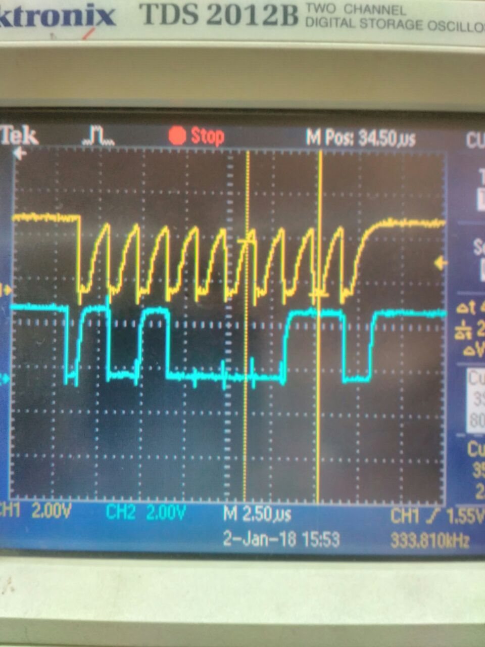
So, after transmitting start, slave write address the acknowledgment has to be given from the sensor in the 9th clock pulse by making the SDA line low which is not happening.

The clock pulses generated are like spikes. Are they correct? Is there anything wrong with the clock pulses.

Can anyone help me to analyze this situation? I have seen this response from the CRO.

  • UCB1I2CSA does not include the R/W bit, so you should set it to the nominal address, i.e. 0x28. The R/W bit is generated from UCTR. (Back in the bad old days, there were a few device data sheets which included the R/W bit; for those one needed to shift the nominal address Right to get the correct I2CSA. I haven't seen one of those recently.)

    The SCL trace doesn't look great, but is probably adequate. It's a bit odd that SDA looks so much cleaner. If you're concerned, you can (a) strengthen the pullup and/or (b) slow down the bus (BR0).

    I haven't tried hitting the I2C unit with a Stop immediately after a Start. The scope seems to say it's OK, but maybe it's worth putting a delay in between, just to reduce the number of variables.
  • Please provide the exact humidity sensor being used and keep in mind that some slave devices can respond to different slave addresses based on the logic level on dedicated pins.

    Regards,
    Ryan
  • Mr. Ryan the sensor is HYT271 humidity and temperature sensor. But I want to only read the humidity bytes. Here I am attaching the data sheet. 

    My default address for the slave (0x28), write address(0x50) and read address (0x51). I have I have set I2CSA=0X28 (nominal address)    as per the example is given by TI there is no

    clock and data seen. Then I have set it to write address (0x50) and the response is shown as below CRO screenshot. 

    I have set I2CSA=0X50

    (7bit address for 0x50 =1010000)


    Is the configuration correct? and also

    •   Why the 8bit is high (1) in CRO but it should be low (0)
    •   Why there is no acknowledgment from the slave i.e 9th bit on SDA line should be low

    How to get the acknowledgment. Please suggest the right configuration register for the slave write and read.


    hyt-manual.pdf

  • Hi Swaroop,

    UCB1I2CSA should be equal to 0x28 and UCTR should be reset for receiver mode, which results in a high read/write bit. The first eight bits should therefore be 01010001b, and if this is properly supplied then the HYT271 will acknowledge by pulling the data line low for the ninth clock. You should not generate the stop condition until you've actually received the necessary data bytes from the humidity sensor, please refer to the msp430x24x_uscib0_i2c_10.c example. Also note that the recommended pull-up resistances are 2.2 kOhm.

    Regards,
    Ryan
  • Dear Ryan, I have tried initially by setting I2CSA=0x28 (default slave address) but the humidity module but there are no traces observed on CRO.

    And as you said, as per the code example I have changed my code
    --------------------------------------------------------
    #include <msp430.h>

    unsigned char *PRxData; // Pointer to RX data
    unsigned char RXByteCtr;
    volatile unsigned char RxBuffer[128]; // Allocate 128 byte of RAM

    int main(void)
    {
    WDTCTL = WDTPW + WDTHOLD; // Stop WDT
    P5SEL |= 0x06; // Assign I2C pins to USCI_B0
    UCB1CTL1 |= UCSWRST; // Enable SW reset
    UCB1CTL0 = UCMST + UCMODE_3 + UCSYNC; // I2C Master, synchronous mode
    UCB1CTL1 = UCSSEL_2 + UCSWRST; // Use SMCLK, keep SW reset
    UCB1BR0 = 12; // fSCL = SMCLK/12 = ~100kHz
    UCB1BR1 = 0;
    UCB1I2CSA = 0x28; // Slave Address is 028h
    UCB1CTL1 &= ~UCSWRST; // Clear SW reset, resume operation
    UC1IE|= UCB0RXIE; // Enable RX interrupt

    while (1)
    {
    PRxData = (unsigned char *)RxBuffer; // Start of RX buffer
    RXByteCtr = 4; // Load RX byte counter
    while (UCB1CTL1 & UCTXSTP); // Ensure stop condition got sent
    UCB1CTL1 |= UCTXSTT; // I2C start condition
    __bis_SR_register(CPUOFF + GIE); // Enter LPM0 w/ interrupts
    // Remain in LPM0 until all data
    // is RX'd
    __no_operation(); // Set breakpoint >>here<< and
    } // read out the RxBuffer buffer
    }

    //-------------------------------------------------------------------------------
    // The USCI_B0 data ISR is used to move received data from the I2C slave
    // to the MSP430 memory. It is structured such that it can be used to receive
    // any 2+ number of bytes by pre-loading RXByteCtr with the byte count.
    //-------------------------------------------------------------------------------
    #if defined(__TI_COMPILER_VERSION__) || defined(__IAR_SYSTEMS_ICC__)
    #pragma vector = USCIAB1TX_VECTOR
    __interrupt void USCIAB1TX_ISR(void)
    #elif defined(__GNUC__)
    void __attribute__ ((interrupt(USCIAB1TX_VECTOR))) USCIAB1TX_ISR (void)
    #else
    #error Compiler not supported!
    #endif
    {
    RXByteCtr--; // Decrement RX byte counter
    if (RXByteCtr)
    {
    *PRxData++ = UCB1RXBUF; // Move RX data to address PRxData
    if (RXByteCtr == 1) // Only one byte left?
    UCB1CTL1 |= UCTXSTP; // Generate I2C stop condition
    }
    else
    {
    *PRxData = UCB1RXBUF; // Move final RX data to PRxData
    __bic_SR_register_on_exit(CPUOFF); // Exit LPM0
    }
    }

    My questions:
    1. No traces observed with I2C1SA=0X28
    2. Configuration to write the byte (0x50) to the sensor and read the byte from the sensor
    3. How to use UCTR in the above code


    Please help me out.


    Regards,
    Swaroop.
  • I don't know of a mechanism wherein the particular setting of I2CSA (in itself) causes the I2C unit to send/not send the address byte. I suspect there's something else going on.

    What board are you using? (I don't recall a commodity board that uses the F2471.) Is the sensor the only (other) unit on the I2C bus? How are you triggering your scope?

    Your previous program was probably a better test case. Did you try it with I2CSA=0x28?
  • Yes,  I have tried it with I2CSA=0X28 and the sensor is not giving any output on the oscilloscope.

    I cannot suspect the sensor because I have got the reading by using the I/O lines(bit banging) and read the data from the sensor.

    And the board is custom board designed by me and it is working with bit banging. I have used pull up resistances of 3.32K which is in the specified range.

    I have triggered the scope of both SCL and SDA lines. The screenshot is already posted by me in the previous message on (Jan 3, 2018, 5:38 PM) with I2CSA=0X50 but not getting with I2CSA=0X28.

    So, please suggest me the solution.

    Thanks and Regards,

    Swaroop.

  • One quick note, the code example provided uses UCB0RXIE instead of UCB1RXIE. They correspond to the same value so it actually will not affect your operation. Like Bruce, I have never heard of the USCI failing to send the slave addressed based on the contents of I2CSA. Does the start condition even get sent? Please provide a screenshot for reference. What happens if you disconnect the sensor from the bus and scope the MSP430 I2C output?

    Regards,
    Ryan

**Attention** This is a public forum