This thread has been locked.

If you have a related question, please click the "Ask a related question" button in the top right corner. The newly created question will be automatically linked to this question.

MSP430F6779: Design guide required for beginner

Part Number: MSP430F6779
Other Parts Discussed in Thread: MSP-EM-DESIGN-CENTER, EVM430-F6779, MSP-TS430PEU128, MSP-FET

Hi

I'm trying to build an energy meter. I choose the MSP430f677x series as a micro controller for this purpose.

Earlier I have been only working around ready made controllers such as r-pi or MSP432E4 eval board. This time I would like to create my own microcontroller board using MSP430f6779. Can someone help me with the following questions?

  • I would like to know what are the external components required for the micro controller(Like crystal oscillator). A basic circuit diagram would be helpful.
  • I would like to know how to burn program on to the micro controller. Is any extra component required for USB debugger interface?(I don't have JTAG debugger)

  • The RESET pin needs an RC filter; see table 1-3 of the User's Guide.

    All power supplies need the usual decoupling capacitors. The VCORE pins needs a 470 nF capacitor; see "Recommended Operating Conditions" in the datasheet. Also see "Auxiliary Supplies Recommended Operating Conditions".

    If you're using the SD24 module, VREF needs a capacitor; see "SD24_B Power Supply and Recommended Operating Conditions".

    You need a crystal only if you need a clock that is more accurate than any of the internal clocks.

    The F6779 does not have a USB interface. For debugging, you need to connect to either the JTAG or the Spy-Bi-Wire pins, and use an emulator device that speaks one of those protocols. Any recent LaunchPad board contains such an emulator, and allows to connect to an external device's SBW pins.
  • Hi Mr.Ladisch

    Thanks for your quick reply. Now I have to make a choice between buying a FET debugger or some other IC. Can you kindly answer the following questions.


    1. Is there any energy meter IC which supports SWD mode?

    2. I have came across an IC in analog devices for energy meter(AD7878) which can calculate active and reactive power directly. I would still need a micro controller to drive the IC and for other operations. Can you recommend some msp or equivalent IC which supports SWD mode to use with this IC?

  • MSP430's SBW (Spy-Bi-Wire) is not the same as ARM's SWD (Serial Wire Debug).

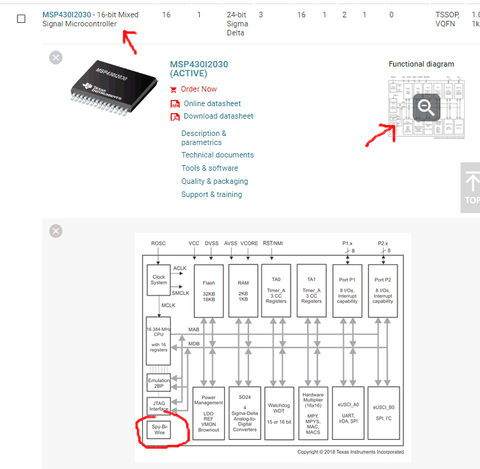
    Only very old MSPs do not support SBW. Anyway, to check if a chip supports SBW, look at the Functional Diagram:

    I do not know what features an energy meter MCU would need, but TI appears to have lots of information about this.

  • I know that MSP430's SBW (Spy-Bi-Wire) is not the same as ARM's SWD (Serial Wire Debug). I notice that in few IC(in MSP432 series) which has SWD along with J-TAG(Like MSP432P401R) and I was wondering if MSP430's has SWD as well.

    Anyway thanks for your input
  • Hello Prakash,

    Thanks for your interest in our MSP430F677x(A) devices! Since you're trying to build an energy meter, there are several valuable resources that I want to highlight for your development.

    First, take a look at our newly-released Energy Measurement Design Center (EMDC) for MSP430 MCUs (MSP-EM-DESIGN-CENTER). It supports these devices and will accelerate your development. Using the GUI, you can quickly configure your system from the ground up or base it on one of the provided EMDC example projects. Later this week, we'll be releasing a new version (v1.30) with a few bug fixes, improved documentation with an added out-of-box-example section, updated communication connections, IAR support, and also support for Rogowski Coils. Start with the Technology Guide.

    Next, you'll need hardware to evaluate the MSP430. Take a look at the EVM430-F6779. It's supported by EMDC and can be used for developing single-phase, two-phase, or three-phase e-meter configurations.

    Lastly, you can also order the target development board (MSP-TS430PEU128) for the MSP430F6779(A) if you'd like to take a simpler development approach. Plus, the target board is an excellent reference since it contains the basic circuitry for programming and debugging the MSP430. This would be an adequate reference for a simple board, but for an actual e-meter, I'd recommend referencing the EVM430-F6779 design.

    For the debugger, I would recommend that you purchase the MSP-FET.

    I hope this helps!

    Regards,

    James

    MSP Customer Applications

  • Dear james

    Sorry for the late reply. Thank you for your input!

    I have gone through the design document of EVM430-F6779. In the power supply section(3.1.2) I notice that the switching power supply (using VSK-3.3V power converter) schematic only uses phase 3 alone as input. I would like to know the possibilty of connecting all phases as input(I know I can't use diode as it will rectify. any other sugestions?).

    I intend to use CT for current measurement. Is any other circuit required between the CT and ADC channel(like input protection?) 

    Regards

    Prakash

  • Hello Prakash,

    Prakash Ramamoorthy20 said:
    Sorry for the late reply. Thank you for your input!

    No problem!

    Prakash Ramamoorthy20 said:
    I have gone through the design document of EVM430-F6779. In the power supply section(3.1.2) I notice that the switching power supply (using VSK-3.3V power converter) schematic only uses phase 3 alone as input. I would like to know the possibilty of connecting all phases as input(I know I can't use diode as it will rectify. any other sugestions?).

    Nice job. Yes, you're correct that the switching power supply does only use one out of the three phases. Is there a reason that you would need all three phases to power the supply? A single phase should have more than enough power for the supply. However, an alternative would be to use the Resistor Capacitor (RC) power supply configuration that allows all three phases to contribute to the current drive, which is approximately three times the drive available from only one phase. According to the EVM's User's Guide, if even higher output drive is required, the same circuitry in Figure 3 can be used followed by an NPN output buffer. Another option would be to replace the RC power supply with a transformer-based power supply.

    Prakash Ramamoorthy20 said:
    I intend to use CT for current measurement. Is any other circuit required between the CT and ADC channel(like input protection?) 

    That's fine. The EVM430-F6779 features three CTs mounted to the case underneath the PCB. Besides the burden resistor, other important parts of the analog front end circuitry include ESD diodes, TVS diodes, and anti-aliasing filters. Take a look at Figure 6 and the schematic. For the most part, if you change CTs and a maximum current, then you'll need to resize the burden resistor accordingly. The CT parameters in EMDC will automatically calculate the CTs' RMS output voltage, convert it to peak voltage, and then compare it to the max input voltage for the MSP430's ADCs. We've tried to make that easier for users.

    I hope this helps.

    Regards,

    James

    MSP Customer Applications

  • James Evans said:

    Is there a reason that you would need all three phases to power the supply?

    The meter should be working even if any one of the phases are out(which likely to happen).

    Any way thanks for your detailed input.

**Attention** This is a public forum