This thread has been locked.

If you have a related question, please click the "Ask a related question" button in the top right corner. The newly created question will be automatically linked to this question.

MSP430AFE253: Simple single-phase energy meter

Part Number: MSP430AFE253
Other Parts Discussed in Thread: MSP430I2041, TIDM-3OUTSMTSTRP, , MSP-EM-DESIGN-CENTER

Hi,

I'm trying to create a simple energy meter that have also the option to switch on/off the load power using 2 relays.

The energy meter works just fine as long as I do not switch on the relays with a load on. Once I'm issuing the command to turn the relays ON, the microcontroller gets fried.

I have tried also with a current transformer, but the results are the same, except that the microcontroller gets fried after 3-4 ON commands.

The shunt resistor is very close the relay that switches the N line, but the N line is switched ON first and than the L line is switched ON after the zero crossing is detected.

I'm attaching an image with the analog front end.

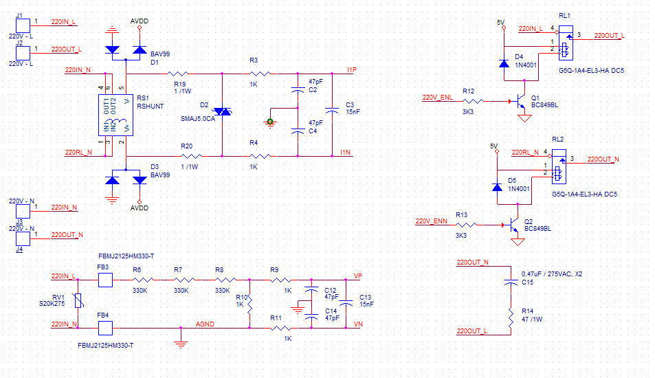
The power supply that supplies the voltages for the design is an AC/DC non-isolated converter.

Is there a way to isolate the damaging effect that the relays induce once they are switched ON?

Best regards,

Cristian

  • Hello Cristian,

    Thanks for your detailed post. At a high level, I'm not sure why you'd need two relays in series here. One relay will interrupt the current flow, so two are not necessary. If you think two are necessary, then try switching them at the same time. I'm concerned that the time between when the two relays are turned on, there's a point where high voltage as applied to the shunt because not current is flowing yet. For example, on a ground-side switch, there is actually voltage AFTER the load because no current is flowing through it when the switch is open. As soon as the ground-side switch is closed connecting the ground, the voltage disappears after the load because it's getting dropped by the current flowing through the load. I wonder if something like that is happening here damaging the MSP430.

    Now, I see that you've got some clamping and TVS diodes on the current channel inputs. That's great. I'd recommend checking for any voltage spikes at the device to determine if the diodes are capable of protecting the device when the relays are turned on.

    For the power relays, I see you're using the G5Q-EL3 series. Looking at the Omron product map, perhaps the G5Q-EL2 series would be better since they appear to have been developed specially for high inrush resistance.

    Take a look at our Three Output Smart Power Strip Reference Design (TIDM-3OUTSMTSTRP) based on the similar MSP430i2041. Looking at the schematic, I see the designers used some large (220uF) capacitors around the relays and also many large, high energy varistors connecting both Line and Neutral to Earth ground. Perhaps these things (and perhaps others that I may have overlooked in this design) will also help resolve your issue.

  • As a follow-up, have you considered using the newer MSP430i2041 in your design? It's very similar to the MSP430AFE253 but features more RAM and Flash memory and an additional SD ADC channel. Also, you can leverage our new Energy Measurement Design Center (EMDC) for MSP430 MCUs (MSP-EM-DESIGN-CENTER) that can accelerate your design and development time. EMDC features an easy-to-use GUI with example projects that allow users to quickly make changes based on their designs, generate code, calibrate their system, and view results measured by the MSP430 running the Energy Measurement software library. You can learn more about EMDC from the following thread and links.

    [FAQ] MSP-EM-DESIGN-CENTER: Announcing the new Energy Measurement Design Center (EMDC) and Software Library for MSP430 MCUs!

    Get started on your development today!

    Energy Measurement Design Center for MSP430 MCUs

    Energy Measurement Technology Guide

  • Hi James,
    Thank you for answering to my problem!

    I need 2 relays because I want to decouple both AC lines from the output socket (just for protection). I just realize that the relays I'm using are not quite the ones that I need, the working current should be as much as 10A, so the EL3 type that I'm using currently is working with 3A and the suggested EL2 type only supports 1A. I will have to find other relays, but the problem remains the same.

    I have studied the application note you suggested and I discover some differences against my design:
    - a TVS diode is also used for voltage divider and it is specified in the app note that is even more important than the one from the shunt resistor path;
    - the AC voltage divider is using resistors with 2512 case, in my design I'm using only 0805 case;
    - there are some varistors attached between the output outlets lines and the earth line. Is this a good practice, to have the varistors tied from N and L lines to earth line? I'm asking this beacause in all the app notes that I reviewed the varistors were placed only between N and L lines.
    I'm not sure if BAV99 is handling the spikes, in other app notes the clamping diodes used are 1N4148 in MELF case.
  • Cristian Dinca said:
    I need 2 relays because I want to decouple both AC lines from the output socket (just for protection). I just realize that the relays I'm using are not quite the ones that I need, the working current should be as much as 10A, so the EL3 type that I'm using currently is working with 3A and the suggested EL2 type only supports 1A. I will have to find other relays, but the problem remains the same.

    Nice catch! Good luck finding one that meets your requirements.

    Cristian Dinca said:
    a TVS diode is also used for voltage divider and it is specified in the app note that is even more important than the one from the shunt resistor path

    Yes, this is very important to protect the MSP430 device from voltage spikes (which are more likely to happen) across R15. Since your design is missing the TVS diode, I suspect this is what's damaging the device when switching relays on/off. I'd recommend taking a new undamaged board and remove all the upper voltage divider resistors (R8 at the minimum). Then, power cycle the relays and see whether the device gets damaged or not. If not, then the missing TVS diode is most likely the issue.

    Cristian Dinca said:
    the AC voltage divider is using resistors with 2512 case, in my design I'm using only 0805 case

    The reason behind using large 2512 resistors is not to conduct more current or power through them but instead the large physical size is leveraged to increase the distance separating the high voltages dropped by the divider. For an input voltage of 220V, each upper 330kOhm resistor drops approximately 75V. If you're using a smaller 0805 resistor, the distance between the pads are much closer. Thus, there would be higher chances of a short between those pads from excessive solder or arcing.

    Cristian Dinca said:
    there are some varistors attached between the output outlets lines and the earth line. Is this a good practice, to have the varistors tied from N and L lines to earth line? I'm asking this beacause in all the app notes that I reviewed the varistors were placed only between N and L lines.

    Yes, this is a good practice. In the Three Output Smart Power Strip Reference Design (TIDM-3OUTSMTSTRP), the varistors are configured in a way that connects the L and N lines to earth AND connects L and N lines together. I would assume that this configuration exists to support instances when earth ground is connected or not through the SOC4 AC plug.

    Cristian Dinca said:
    I'm not sure if BAV99 is handling the spikes, in other app notes the clamping diodes used are 1N4148 in MELF case.

    This is a good observation. However, the BAV99 features two integrated diodes in series whereas the 1N4148 diodes are discrete components in series. While the TIDM-3OUTSMTSTRP design doesn't have these clamping diodes, I would highly recommend them to the differential inputs. The varistors are excellent for fast transients, but these clamping diodes will add additional system-level protection for longer pulses on these inputs.

    I hope this helps!

    Regards,

    James

**Attention** This is a public forum