This thread has been locked.
If you have a related question, please click the "Ask a related question" button in the top right corner. The newly created question will be automatically linked to this question.
Part Number: MSP432P401R
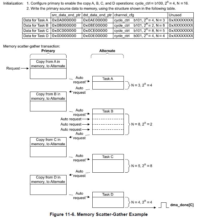
I am interfacing a SPI sensor with DMA, using scatter-gather mode. There must be something I am missing here.
To fetch 192 bytes from sensor FIFO, I filled a table of tasks, each one being an element of type DMA_ControlTable. Such table is reported below; with 385 entries it takes about 6 kB, yet I have enough memory for it:
/* SPI readout DMA sequence */ DMA_ControlTable SpiAccReadoutSeq[N_OF_ACC_DMA_TASKS];
The sequence tends to repeat the same tasks, just changing few parameters; therefore I wrote the following code to quickly initialize the tasklist:
// Spi readout tasks DMA_ControlTable SendAccReadoutAddr = DMA_TaskStructEntry(1, UDMA_SIZE_8, UDMA_SRC_INC_NONE, &AccOutputAddr, UDMA_DST_INC_NONE, &SPI_Module_Address->TXBUF, UDMA_ARB_1, (UDMA_MODE_MEM_SCATTER_GATHER+UDMA_MODE_ALT_SELECT)); DMA_ControlTable SendFirstDummyByte = DMA_TaskStructEntry(1, UDMA_SIZE_8, UDMA_SRC_INC_NONE, &dummyTx, UDMA_DST_INC_NONE, &SPI_Module_Address->TXBUF, UDMA_ARB_1, (UDMA_MODE_PER_SCATTER_GATHER+UDMA_MODE_ALT_SELECT)); DMA_ControlTable SendDummyByte = DMA_TaskStructEntry(1, UDMA_SIZE_8, UDMA_SRC_INC_NONE, &dummyTx, UDMA_DST_INC_NONE, &SPI_Module_Address->TXBUF, UDMA_ARB_1, (UDMA_MODE_MEM_SCATTER_GATHER+UDMA_MODE_ALT_SELECT)); DMA_ControlTable RetrieveByteFromAcc = DMA_TaskStructEntry(1, UDMA_SIZE_8, UDMA_SRC_INC_NONE, &SPI_Module_Address->RXBUF, UDMA_DST_INC_NONE, &AccDataBuffer[0], UDMA_ARB_1, (UDMA_MODE_PER_SCATTER_GATHER+UDMA_MODE_ALT_SELECT)); DMA_ControlTable RetrieveLastByteFromAcc = DMA_TaskStructEntry(1, UDMA_SIZE_8, UDMA_SRC_INC_NONE, &SPI_Module_Address->RXBUF, UDMA_DST_INC_NONE, &AccDataBuffer[ACC_DATA_BUFFER_LEN - 1], UDMA_ARB_1, UDMA_MODE_BASIC); SpiAccReadoutSeq[0] = SendAccReadoutAddr; SpiAccReadoutSeq[1] = SendFirstDummyByte; SpiAccReadoutSeq[2] = RetrieveByteFromAcc; for(i = 3; i < N_OF_ACC_DMA_TASKS; i += 2) { SpiAccReadoutSeq[i] = SendDummyByte; if(i == N_OF_ACC_DMA_TASKS - 2) break; SpiAccReadoutSeq[i+1] = RetrieveByteFromAcc; SpiAccReadoutSeq[i+1].dstEndAddr = &AccDataBuffer[(i-1)/2]; } SpiAccReadoutSeq[N_OF_ACC_DMA_TASKS - 1] = RetrieveLastByteFromAcc;
DMA is being configured as follows:
/* DMA Control Table */ #if defined(__TI_COMPILER_VERSION__) #pragma DATA_ALIGN(DmaControlTable, 1024) #elif defined(__IAR_SYSTEMS_ICC__) #pragma data_alignment=1024 #elif defined(__GNUC__) __attribute__ ((aligned (1024))) #elif defined(__CC_ARM) __align(1024) #endif static DMA_ControlTable DmaControlTable[16];
// Enable DMA DMA_enableModule(); // Assign the control table DMA_setControlBase(DmaControlTable); // Configure DMA transfer DMA_setChannelControl(DMA_WIRED_UART_TX_CH|UDMA_PRI_SELECT, UDMA_SIZE_8 | UDMA_SRC_INC_8 | UDMA_DST_INC_NONE | UDMA_ARB_1); DMA_setChannelControl(DMA_WIRED_UART_RX_CH|UDMA_PRI_SELECT, UDMA_SIZE_8 | UDMA_SRC_INC_NONE | UDMA_DST_INC_8 | UDMA_ARB_1); DMA_setChannelControl(DMA_OPTICAL_UART_TX_CH|UDMA_PRI_SELECT, UDMA_SIZE_8 | UDMA_SRC_INC_8 | UDMA_DST_INC_NONE | UDMA_ARB_1); DMA_setChannelControl(DMA_OPTICAL_UART_RX_CH|UDMA_PRI_SELECT, UDMA_SIZE_8 | UDMA_SRC_INC_NONE | UDMA_DST_INC_8 | UDMA_ARB_1); DMA_setChannelControl(DMA_APPEND_PACKET_CH|UDMA_PRI_SELECT, UDMA_SIZE_8 | UDMA_SRC_INC_8 | UDMA_DST_INC_8 | UDMA_ARB_1024); // Assign channels DMA_assignChannel(DMA_OPTICAL_UART_TX_CH); DMA_assignChannel(DMA_WIRED_UART_TX_CH); DMA_assignChannel(DMA_OPTICAL_UART_RX_CH); DMA_assignChannel(DMA_WIRED_UART_RX_CH); DMA_assignChannel(DMA_SPI_TX_CH); DMA_assignChannel(DMA_SPI_RX_CH); DMA_assignChannel(DMA_APPEND_PACKET_CH); // Clear IFG register DMA_Channel->INT0_CLRFLG = 0xFFFFFFFF; // Assign interrupt to specific DMA ISR DMA_assignInterrupt(INT_DMA_SPI, DMA_SPI_RX_CH_NUM); // Clear specific DMA interrupt flag before enabling DMA_clearInterruptFlag(DMA_SPI_RX_CH & 0x0F); // Enable SPI DMA interrupt DMA_enableInterrupt(INT_DMA_SPI);
void FetchInertialData(SpiDeviceHandle *Handle) { // Timeout counter volatile uint16_t Timeout; // Let some time pass before starting a data transfer Timeout = Handle->CsInterval_T; while(--Timeout); // Preload setup time Timeout = Handle->setup_T; // Clear Spi Rx interrupt flag Handle->SpiModuleAddress->IFG &= ~SPI_RECEIVE_INTERRUPT_FLAG; // Lower CS GPIO_setOutputLowOnPin(Handle->CsPort, Handle->CsPin); // Wait setup time while(--Timeout); // Perform data fetching in scatter-gather mode if(Handle == &AccSpiHandle) DMA_setChannelScatterGather(DMA_SPI_RX_CH, N_OF_ACC_DMA_TASKS, SpiAccReadoutSeq, 0); DMA_enableChannel(DMA_SPI_RX_CH_NUM); DMA_requestSoftwareTransfer(DMA_SPI_RX_CH_NUM); }
Spi peripheral works perfectly fine, reading and writing sensor settings at startup. The problem arises when I try fetching external FIFO contents via the DMA: MOSI and MISO do not move, and counting SCK pulses on the oscilloscope I see barely 10 byte transfer attempts. DMA_INT1 triggers properly, apparently too early. I suspect that something is wrong with triggers, and some tasks simply overlap, but I can't see why right now.
Any clues?
Hello Chris,
let me check if I grasped the concept behind the scatter-gather triggering thing:
What's the limit for the tasks list length?
Looking at the trace I posted, it is clear that the software trigger actually triggers something (SCLK runs for quite long and DMA ISR is entered). I went for software trigger because I was unable to see whatsoever effect by manually driving the interrupt flag, and that's the typical way to start an AUTO mode memory-to-memory DMA transfer, as tasks loading is. I reorganized the tasklist and corrected the code according to the four points above, yet I still can't retrieve data, and the data transfer does not even seem to start.
Let's recap what I am trying to do, I must have done some silly mistake that keeps hiding in plain light.
#define ACC_DATA_BUFFER_LEN INERTIAL_FIFO_DEPTH * ACCELEROMETER_ACTIVE_AXES * INERTIAL_DATA_SIZE /* DMA Control Table */ #if defined(__TI_COMPILER_VERSION__) #pragma DATA_ALIGN(DmaControlTable, 1024) #elif defined(__IAR_SYSTEMS_ICC__) #pragma data_alignment=1024 #elif defined(__GNUC__) __attribute__ ((aligned (1024))) #elif defined(__CC_ARM) __align(1024) #endif DMA_ControlTable DmaControlTable[16]; /* SPI readout DMA sequence */ DMA_ControlTable SpiAccReadoutSeq[N_OF_ACC_DMA_TASKS]; /* Inertial data buffers */ volatile uint8_t AccDataBuffer[ACC_DATA_BUFFER_LEN]; /* DMA-related memory locations and constants */ const uint8_t dummyTx = 0x00; volatile uint8_t dummyRx; /* Sensors output addresses */ const uint8_t AccReadOutputAddr = LIS3DSH_OUT_X_L_ADDR | (1 << 7);
#define DMA_SPI_RX_CH DMA_CH5_EUSCIB1RX1 #define DMA_SPI_RX_INT_FLAG DMA_INT0_SRCFLG_CH5 #define DMA_SPI_RX_CH_NUM DMA_CHANNEL_5 // Enable DMA DMA_enableModule(); // Assign the control table DMA_setControlBase(DmaControlTable); // Assign channels // [...] DMA_assignChannel(DMA_SPI_RX_CH);
#define INT_DMA_SPI INT_DMA_INT1 // Clear IFG register DMA_Channel->INT0_CLRFLG = 0xFFFFFFFF; // Assign interrupt to specific DMA ISR DMA_assignInterrupt(INT_DMA_SPI, DMA_SPI_RX_CH_NUM); // Clear specific DMA interrupt flag before enabling DMA_clearInterruptFlag(DMA_SPI_RX_CH & 0x0F); // Enable SPI DMA interrupt DMA_enableInterrupt(INT_DMA_SPI); // Connect DMA interrupts to controller Interrupt_enableInterrupt(INT_DMA_INT0); Interrupt_enableInterrupt(INT_DMA_SPI); // Master interrupt Interrupt_enableSleepOnIsrExit(); Interrupt_enableMaster(); // main() idle routine while(1) { PCM_gotoLPM0InterruptSafe(); }
#define N_OF_ACC_DMA_TASKS 2 * INERTIAL_FIFO_DEPTH * ACCELEROMETER_ACTIVE_AXES * INERTIAL_DATA_SIZE + 3 SpiAccReadoutSeq[0] = SendAccReadoutAddr; SpiAccReadoutSeq[1] = ClearRxIfg; for(i = 2; i < N_OF_ACC_DMA_TASKS - 1; i += 2) { SpiAccReadoutSeq[i] = SendDummyByte; SpiAccReadoutSeq[i+1] = RetrieveByteFromAcc; SpiAccReadoutSeq[i+1].dstEndAddr = &AccDataBuffer[(i-2)/2]; } SpiAccReadoutSeq[N_OF_ACC_DMA_TASKS - 1] = DummyMemMove;
// Spi readout tasks DMA_ControlTable SendAccReadoutAddr = DMA_TaskStructEntry(1, UDMA_SIZE_8, UDMA_SRC_INC_NONE, &AccReadOutputAddr, UDMA_DST_INC_NONE, &SPI_Module_Address->TXBUF, UDMA_ARB_1, (UDMA_MODE_MEM_SCATTER_GATHER+UDMA_MODE_ALT_SELECT)); DMA_ControlTable ClearRxIfg = DMA_TaskStructEntry(1, UDMA_SIZE_8, UDMA_SRC_INC_NONE, &SPI_Module_Address->RXBUF, UDMA_DST_INC_NONE, &dummyRx, UDMA_ARB_1, (UDMA_MODE_PER_SCATTER_GATHER+UDMA_MODE_ALT_SELECT)); DMA_ControlTable SendDummyByte = DMA_TaskStructEntry(1, UDMA_SIZE_8, UDMA_SRC_INC_NONE, &dummyTx, UDMA_DST_INC_NONE, &SPI_Module_Address->TXBUF, UDMA_ARB_1, (UDMA_MODE_MEM_SCATTER_GATHER+UDMA_MODE_ALT_SELECT)); DMA_ControlTable RetrieveByteFromAcc = DMA_TaskStructEntry(1, UDMA_SIZE_8, UDMA_SRC_INC_NONE, &SPI_Module_Address->RXBUF, UDMA_DST_INC_NONE, &AccDataBuffer[0], UDMA_ARB_1, (UDMA_MODE_PER_SCATTER_GATHER+UDMA_MODE_ALT_SELECT)); DMA_ControlTable DummyMemMove = DMA_TaskStructEntry(1, UDMA_SIZE_8, UDMA_SRC_INC_NONE, &dummyTx, UDMA_DST_INC_NONE, &dummyRx, UDMA_ARB_1, UDMA_MODE_BASIC);
#define SPI_RECEIVE_INTERRUPT_FLAG EUSCI_B_IFG_RXIFG void FetchInertialData(SpiDeviceHandle *Handle) { // Timeout counter volatile uint16_t Timeout; // Let some time pass before starting a data transfer Timeout = Handle->CsInterval_T; while(--Timeout); // Preload setup time Timeout = Handle->setup_T; // Lower CS GPIO_setOutputLowOnPin(Handle->CsPort, Handle->CsPin); // Wait setup time while(--Timeout); // Perform data fetching in scatter-gather mode if(Handle == &AccSpiHandle) DMA_setChannelScatterGather(DMA_SPI_RX_CH, N_OF_ACC_DMA_TASKS, SpiAccReadoutSeq, 0); DMA_enableChannel(DMA_SPI_RX_CH_NUM); Handle->SpiModuleAddress->IFG |= SPI_RECEIVE_INTERRUPT_FLAG; //DMA_requestSoftwareTransfer(DMA_SPI_RX_CH_NUM); }
I think you have accurately described the scatter-gather triggering. I find it helpful to also look at the diagrams in the TRM.
The limit for the number of tasks is 256. This means that the primary is actually set to 1024, performing 4 transfers (from task list to the alternate data structure) 256 times.
In the Table/Channel assignment you have selected DMA_CH5_EUSCIB1RX1. This is an invalid SPI channel. RX1/TX1,RX2/TX2, and RX3/TX3 only apply to the I2C slave addresses UCBxI2COA1, UCBxI2COA2, and UCBxI2COA3. For UART and SPI only the RX0/TX0 are applicable.
Hope that helps,
Chris
Thanks a lot!
I wouldn't have found this issue in a million years, where is the distinction between SPI/UART and I2C DMA triggers noted on the manual?
Dear Chris,
I know I could test it directly on a breadboard, but maybe you can provide me this information the quickest and most reliable way:
are there any restrictions on DMA channels assignment for UCAx peripherals used in SPI mode?
In this case, being I2C option absent, DMA trigger is the same both for UART and SPI, right?
In my new system design I need more serial links, so I cannot rely solely on UCB SPI peripherals as I have always been doing until now.
Many thanks and regards
**Attention** This is a public forum