This thread has been locked.

If you have a related question, please click the "Ask a related question" button in the top right corner. The newly created question will be automatically linked to this question.

MSP432P401R: LCD- U8G LIBRARY ST7920 FOR 32-bit ARM?

Part Number: MSP432P401R

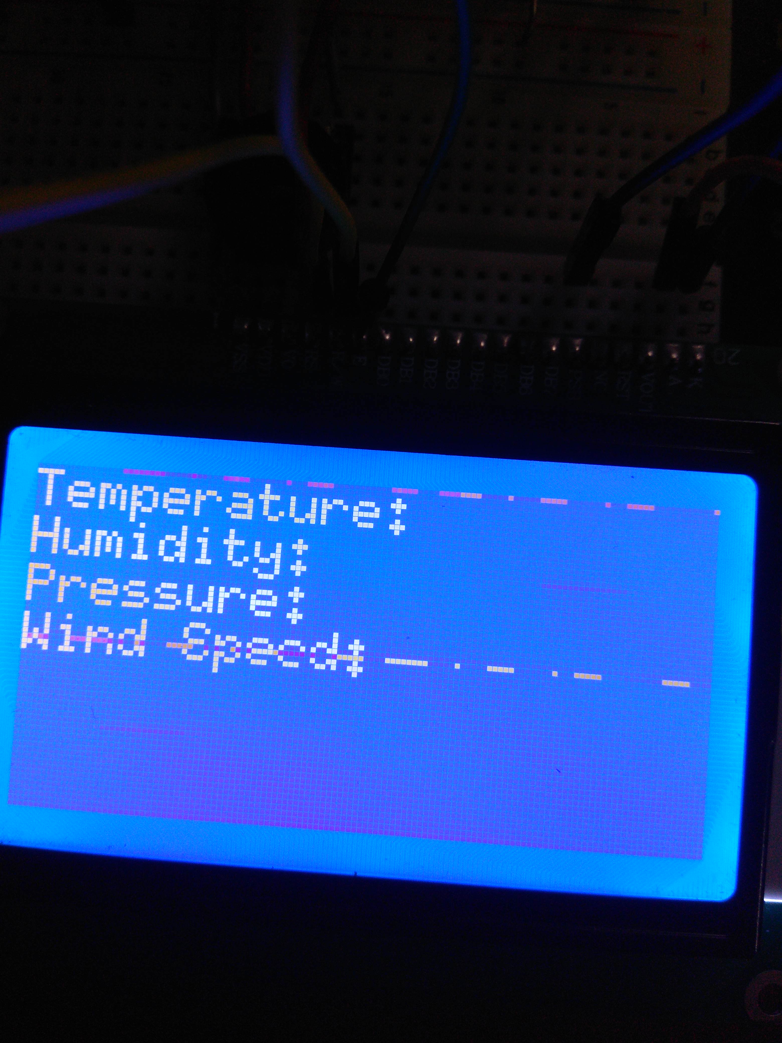
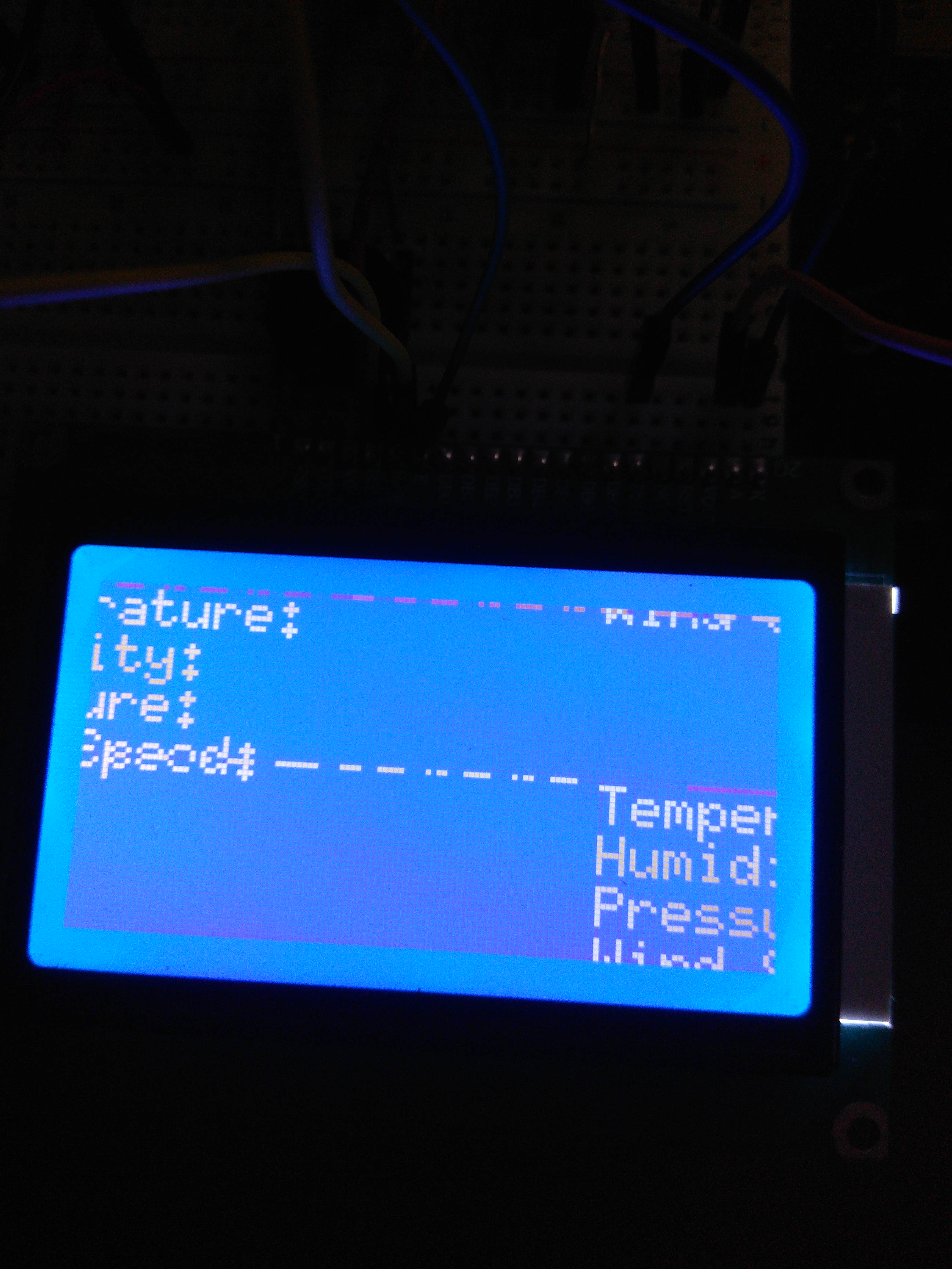
Hi, i am making a project and i need to visualize data on an LCD 12864 ZW with ST7920 ..   i previously used this with the U8G library for arduino and had success...

the problem is i cant find a compatible libray for msp432 and when i try to compile with the library i used in arduino i get the: 

U8g.h: No such file or directory error,though the library lies in the proper folder in Libraries...

So, is there a way to use this lcd WITH ENERGIA with a compatible library for the msp432?

Energia 1.8.7E21
Windows 10 x64


THANKS, GIO.

  • Hi Gio,
    may you can share some more details about which library are you using and where you did get the U8G library.
    I assume you used the library manager but when i look into Arduino there are some more with similar names but none with U8G only.


    Thanks,
    Stefan
  • Hi Stefan,
    i installed the u8glib Version 1.19.1 by Oliver Kraus from Arduino>Manage Libraries...that same library is not working with the MSP, meaning that i get the error i mentioned above...
    This library is no more supported as the man states in his github...so i will try with the u8g2 and come back later...
    i am posting the library here:
    U8glib.rar

  • Hi Gio,

    i did an compile with the example full_buffer - GraphicsTest.
    There are a few small update required to get it compiled:
    in the ino file i used this version of LCD (line needs to be uncommented):
    U8G2_ST7920_128X64_F_HW_SPI u8g2(U8G2_R0, /* CS=*/ 10, /* reset=*/ 8);

    In U8x8lib.cpp
    replace:
    yield();
    with:
    Task_yield();


    In U8x8lib.cpp
    replace (on several places in the file)
    #if ARDUINO >= 10600
    with
    #if xARDUINO >= 10600

    => this is to use the older version of the SPI library without SPI.beginTransaction support which is not available now in the MSP432

    Regards,
    Stefan
  • so i downloaded the available u8g2 libraries from arduino libraries manager , v2.0.6, v2.0.7 and v2.1.5 these are the only available libraries that do NOT implement beginTransaction for SPI.
    the lines you point me though do not exist in any of these libraries on .cpp or .h ,but they compile even without editing, although i cant get it to work properly..ill try again tomorrow and i ll keep in touch...maybe you can attach the library you used or point me the version you used?
    thanks again for the response man!
  • Hi Gio,

    i have used Arduino 1.6.8 and it offered me u8g2 library version 2.24.3 as latest version.

    ~ Stefan

  • Stefan Schauer said:

    => this is to use the older version of the SPI library without SPI.beginTransaction support which is not available now in the MSP432

    i thought you used an older u8g2 library that do not use SPI.beginTransaction...

    i tried the latest one and did the editing you mentioned and its working!!

    thanks again,you are my hero!!

  • so Stefan, i got the LCD to work when i run the code without any other SPI devices...
    The thing is that i need to use 4 PT100 for temperature readings going into 4 different adafruit's MAX31865 devices that all comunicate through SPI with my MSP432.

    That means that these 5 devices share CLOCK and SDI (data in) and they receive  or send data when the CS is active...SDO is  needed in LCD though the MAX is using it..

    So, the problem is that the LCD is not doing what it should be  when i run multiple SPI devices ( even with 2 spi devices,one being the LCD)..

    My guess is that the LCD gets more data than it should..could it be that MAX31865 end and beginTransaction code we modified messing with the timings/data sent?
    the reason im saying this is because i see in the display dots(pixels) in a line that remind me of bytes packages that the MAX would send to the MSP..can you help me or at least point me the way i should approach this/what to search for? this is for my thesis and i need it done with MSP432.
    take a look in the pictures below to understand my way of thinking:
    thanks for your time, Gio.

  • Hi Gio,

    How do you have connected the LCD to the MSP432, esp. the Chip Select line.
    How have you connected the MAXxxxx device to the MSP432.

    When accessing the different devices on the SPI bus how do you open the SPI interface, e.g.
    SPI.begin()
    SPI.setModule()

    ~ Stefan
  • Hi again and thank you for your quick response,

    I use Hardware SPI for both and have a different CS lines for each of them.

    see code and correct me if im wrong:

    int CS1=11,CS2=12,CS3=13,CS4=17;//MAX CS
    
    U8G2_ST7920_128X64_F_HW_SPI u8g2(U8G2_R2, /* CS=*/ 40, /* reset=*/U8X8_PIN_NONE );
    
    Adafruit_MAX31865 max_1 = Adafruit_MAX31865(CS1);
    Adafruit_MAX31865 max_2 = Adafruit_MAX31865(CS2);
    Adafruit_MAX31865 max_3 = Adafruit_MAX31865(CS3);
    Adafruit_MAX31865 max_4 = Adafruit_MAX31865(CS4);

    so until now, i did this inside void loop(void) to call for SPI

    //PT1
      digitalWrite(CS1, LOW); 
      uint16_t rtd1 = max_1.readRTD();
      float ratio1 = rtd1;
      ratio1 /= 32768;
      pt1=max_1.temperature(100, RREF);
      //Serial.println(pt1);
      digitalWrite(CS1, HIGH); 
    //PT2    
      digitalWrite(CS2, LOW); 
      uint16_t rtd2 = max_2.readRTD();
      float ratio2 = rtd2;
      ratio2 /= 32768;
      pt2=max_2.temperature(100, RREF);
      //Serial.println(pt2);
    //PT3 
      digitalWrite(CS3, LOW); 
      uint16_t rtd3 = max_3.readRTD();
      float ratio3 = rtd3;
      ratio3 /= 32768;
      pt3=max_3.temperature(100, RREF);
      //Serial.println(pt3);
      digitalWrite(CS3, HIGH); 
    //PT4
      digitalWrite(CS4, LOW); 
      uint16_t rtd4 = max_4.readRTD();
      float ratio4 = rtd4;
      ratio4 /= 32768;
      pt4=max_4.temperature(100, RREF);
      //Serial.println(pt4);
      digitalWrite(CS4, HIGH); 
    //LCD_REFRESH
       u8g2.clearBuffer();
       draw();
       u8g2.sendBuffer();
      

    NOW,i dont know how i didnt noticed before,i replaced LCD_REFRESH with this

    digitalWrite(40,LOW);
    u8g2.clearBuffer();
    draw();
    u8g2.sendBuffer();
    digitalWrite(40,HIGH);

    but i still get some trash in my lcd

    below is the whole code

     //#include "SoftwareSerial.h"
    #include "SPI.h"
    #include "DHT.h"
    #include "MS5611.h"
    #include "Wire.h"
    #include <Arduino.h>
    #include <U8g2lib.h>
    //#include <SPI.h>
    #define U8X8_HAVE_HW_SPI
    //#ifdef U8X8_HAVE_HW_I2C
    //#include <Wire.h>
    //#endif
    #define DHTPIN 33 
    #define DHTTYPE DHT22 
    #define P0 1013.25
    #include <Adafruit_MAX31865.h>
    #define RREF      430.0
    // The 'nominal' 0-degrees-C resistance of the sensor
    // 100.0 for PT100, 1000.0 for PT1000
    #define RNOMINAL  100.0
    
    int CS1=11,CS2=12,CS3=13,CS4=17;
    String F,G;
    float t=0,h=0,pt1=0,pt2=0,pt3=0,pt4=0;
    
    //LCD SPI:E>>CLK, RS>>CS,RW>>MOSI,PSB>>GND
    //V0 to 5V
    //VDD 10KPOT
    //VSS to GND
    U8G2_ST7920_128X64_F_HW_SPI u8g2(U8G2_R2, /* CS=*/ 40, /* reset=*/U8X8_PIN_NONE );
    //PT100-MAX31865 SETUP
    // Use software SPI: CS, DI, DO, CLK
    //Adafruit_MAX31865 max1 = Adafruit_MAX31865(10,11,12,13);
    // use hardware SPI, just pass in the CS pin
    Adafruit_MAX31865 max_1 = Adafruit_MAX31865(CS1);
    Adafruit_MAX31865 max_2 = Adafruit_MAX31865(CS2);
    Adafruit_MAX31865 max_3 = Adafruit_MAX31865(CS3);
    Adafruit_MAX31865 max_4 = Adafruit_MAX31865(CS4);
    DHT dht(DHTPIN, DHTTYPE);
    // MS5611
    MS5611 ms5611;
    double referencePressure;
    
    ////Setup Variables for ANEMOMETER 
    //
    //const int sensorPin = A0; //Defines the pin that the anemometer output is connected to
    //int sensorValue = 0; //Variable stores the value direct from the analog pin
    //float sensorVoltage = 0; //Variable that stores the voltage (in Volts) from the anemometer being sent to the analog pin
    //float windSpeed = 0; // Wind speed in meters per second (m/s)
    //
    //float voltageConversionConstant = .004882814; //This constant maps the value provided from the analog read function,
    ////which ranges from 0 to 1023, to actual voltage, which ranges from 0V to 5V
    //int sensorDelay = 1000; //Delay between sensor readings, measured in milliseconds (ms)
    //
    ////Anemometer Technical Variables
    ////The following variables correspond to the anemometer sold by Adafruit, but could be modified to fit other anemometers.
    //
    //float voltageMin = .4; // Mininum output voltage from anemometer in mV.
    //float windSpeedMin = 0; // Wind speed in meters/sec corresponding to minimum voltage
    //
    //float voltageMax = 2.0; // Maximum output voltage from anemometer in mV.
    //float windSpeedMax = 32; // Wind speed in meters/sec corresponding to maximum voltage
    
    void u8g2_prepare(void) {
      u8g2.setFont(u8g2_font_6x10_tf);
      //u8g2.setFont(u8g2_font_helvR08_tn);
      u8g2.setFontRefHeightText();
      u8g2.setDrawColor(1);
      u8g2.setFontPosTop();
      u8g2.setFontDirection(0);
    }
    //void u8g2_box_frame(uint8_t a) {
    //  u8g2.drawStr( 0, 0, "drawBox");
    //  u8g2.drawBox(5,10,20,10);
    //  u8g2.drawBox(10+a,15,30,7);
    //  u8g2.drawStr( 0, 30, "drawFrame");
    //  u8g2.drawFrame(5,10+30,20,10);
    //  u8g2.drawFrame(10+a,15+30,30,7);
    //}
    
    void draw(void) {
      u8g2_prepare();
      u8g2.drawStr(0,0,"Temperature:");
      u8g2.drawStr(0,9,"Humidity:");
      u8g2.drawStr(0,18,"Pressure:");
      u8g2.drawStr(0,27,"Wind Speed:");
    }
    
    //u8g2.drawFrame(0,0,128,31);            // upper frame
    //u8g2.drawFrame(0,33,128,31);           // lower frame
    ////u8g.drawStr(33,27, temp_string);
    //u8g2.setPrintPos(62,11);
    //u8g2.print(pt1);
    //u8g2.setPrintPos(62,22);
    //u8g2.print(pt1);
    //u8g2.setPrintPos(62,33);
    //u8g2.print(pt1);
    //u8g2.setPrintPos(62,44);
    ////u8g.print(windSpeed);
    //u8g2.drawStr( 92, 11, "*C");
    //u8g2.drawStr( 92, 22, "%");
    //u8g2.drawStr( 105, 33, "mBar");
    //u8g2.drawStr( 92, 44, "m/s");
    
    
    void setup(void){
      // disable LCD SPI
      pinMode(40,OUTPUT);
      digitalWrite(40,HIGH);
      // disable PT1 SPI
      pinMode(CS1,OUTPUT);
      digitalWrite(CS1,HIGH);
      // disable PT2 SPI
      pinMode(CS2,OUTPUT);
      digitalWrite(CS2,HIGH);
      // disable PT3 SPI
      pinMode(CS3,OUTPUT);
      digitalWrite(CS3,HIGH);
      // disable PT4 SPI
      pinMode(CS4,OUTPUT);
      digitalWrite(CS4,HIGH);
    //INIT
      Serial1.begin(9600);
      SPI.begin();
      u8g2.begin();
      dht.begin();
      ms5611.begin();
      max_1.begin(MAX31865_3WIRE);
      max_2.begin(MAX31865_3WIRE);
    //  max_3.begin(MAX31865_3WIRE);
    //  max_4.begin(MAX31865_3WIRE);
      referencePressure = ms5611.readPressure();
      //u8g2.clearDisplay();
      
    }
    
    
    void loop(void){
    
      
      //rebuild the picture after some delay
      //delay(50);
    //dht22
      float t = dht.readTemperature();
      float h = dht.readHumidity();
       
    //MS5611
      // Read raw values
      uint32_t rawPressure = ms5611.readRawPressure();
      // Read true temperature & Pressure
      long realPressure = ms5611.readPressure();
    
    ////ANEMOMETER algorithm
    //sensorValue = analogRead(A0); //Get a value between 0 and 1023 from the analog pin connected to the anemometer
    //
    //sensorVoltage = sensorValue * voltageConversionConstant; //Convert sensor value to actual voltage
    //
    ////Convert voltage value to wind speed using range of max and min voltages and wind speed for the anemometer
    //if (sensorVoltage <= voltageMin){
    // windSpeed = 0; //Check if voltage is below minimum value. If so, set wind speed to zero.
    //}
    //
    //else {
    //  windSpeed = (sensorVoltage - voltageMin)*windSpeedMax/(voltageMax - voltageMin); //For voltages above minimum value, use the linear relationship to calculate wind speed.
    //    }
    //SPI_MANUAL_COMMUNICATION
    //PT1
      digitalWrite(CS1, LOW); 
      uint16_t rtd1 = max_1.readRTD();
      float ratio1 = rtd1;
      ratio1 /= 32768;
      pt1=max_1.temperature(100, RREF);
      //Serial.println(pt1);
      digitalWrite(CS1, HIGH); 
    //PT2    
      digitalWrite(CS2, LOW); 
      uint16_t rtd2 = max_2.readRTD();
      float ratio2 = rtd2;
      ratio2 /= 32768;
      pt2=max_2.temperature(100, RREF);
      //Serial.println(pt2);
    //PT3 
      digitalWrite(CS3, LOW); 
      uint16_t rtd3 = max_3.readRTD();
      float ratio3 = rtd3;
      ratio3 /= 32768;
      pt3=max_3.temperature(100, RREF);
      //Serial.println(pt3);
      digitalWrite(CS3, HIGH); 
    //PT4
      digitalWrite(CS4, LOW); 
      uint16_t rtd4 = max_4.readRTD();
      float ratio4 = rtd4;
      ratio4 /= 32768;
      pt4=max_4.temperature(100, RREF);
      //Serial.println(pt4);
      digitalWrite(CS4, HIGH); 
    //LCD_REFRESH
       digitalWrite(40,LOW);
       u8g2.clearBuffer();
       draw();
       u8g2.sendBuffer();
       digitalWrite(40,HIGH);
       
        F=String('T')+String(t)+String('H')+String(h)+String('P')+String(realPressure)
        +String('T')+String(pt1)+String('T')+String(pt2)+String('T')+String(pt3)+String('T')+String(pt4);
    //F =String('T')+String(t)+String('H')+String(h)+String('P')+String(realPressure)+String('S')+String(windSpeed)+
    //String('T')+String(pt1)+String('T')+String(pt2)+String('T')+String(pt3)+String('T')+String(pt4); 
     
    //Serial.println(t);
    //Serial.println(h);
    //Serial.println(realPressure);
    //Serial.println(windSpeed);
    //Serial.println(F);
        //Serial1.println(F);
     
    
    //delay(1000);
    }


  • HI Gio,

    there are two thing you might check:
    - This line is missing for PT2 block
    digitalWrite(CS2, HIGH);
    => should not solve this problem but might be another one

    - if i got the right info for the LCD driver you are using that should have CS low as deactivated. So your code should be this
    digitalWrite(40,HIGH);
    u8g2.clearBuffer();
    draw();
    u8g2.sendBuffer();
    digitalWrite(40,LOW);

    Where as on my understanding of the driver this already done inside the Graphical driver, so this should be OK
    u8g2.clearBuffer();
    draw();
    u8g2.sendBuffer();

    So back to the beginning and explains why this was working before.
    So to get forward it would be good if you can probe the CS pin for the display with a Oscilloscope and my check with the other CS signals that there is no overlap between them.
    If you do not have that option just try to put the CS line of the display to high (connect to Vcc). In this case the display should not get any update just to see that this works as expected.

    ~ Stefan
  • Hi
    -you were right about the CS being high active but that does not change anything like you said...unfortunately i do not have an oscilloscope right now, and i put the CS line of the display to high and it seems like it is working fine...it prints what i have written in the draw() function without the trash dots...so i am lost right now..if there is an overlap between CS signals what is the next step to eliminate these overlaps?i know i could use hardware like transistors/switches..can i do it software-wise?


    -i have another display which is a TFT with an ili9225 driver(TFT_22_ILI9225 is the library's name ) that i can use,  uses SPI but i need to modify the .cpp, something i am not able to do by myself (YET!).
    the first error i get is the 

    fatal error: pins_arduino.h: No such file or directory

    from what i read i just have to change #include <pins_arduino.h> to #include <pins_energia.h>  in the cpp...but then again there are begin/endTransaction functions which i cant handle... 
    any help would be welcome!

    ~Gio 

  • Hi Gio,

    let us first try the display you just have before changing to another.

    May you can confirm that if you put the CS line to low that the display does not get any updates.

    So we can ensure the CS line is able to disable the display.

    Then as a next step you can try to make the loop shorter to get some more info where the problem could be coming from:

    so may just have this in your loop:

    //PT4
      digitalWrite(CS4, LOW); 
      uint16_t rtd4 = max_4.readRTD();
      float ratio4 = rtd4;
      ratio4 /= 32768;
      pt4=max_4.temperature(100, RREF);
      //Serial.println(pt4);
      digitalWrite(CS4, HIGH); 
    //LCD_REFRESH
       digitalWrite(40,LOW);
       u8g2.clearBuffer();
       draw();
       u8g2.sendBuffer();
       digitalWrite(40,HIGH);

    You may also can try to really control the CS line of the display by yourself with passing 0 as pin for CS when init the LCD

    U8G2_ST7920_128X64_F_HW_SPI u8g2(U8G2_R2, /* CS=*/ 0, /* reset=*/U8X8_PIN_NONE );

    ~ Stefan

  • hi there ,
    i have a similar issue please click on this link

    e2e.ti.com/.../768747
  • Hi Gio,

    could you solve the issue or do you have further questions regarding this topic?
    If solved, please select "Resolved" for the post that solved your issue so this thread can be closed out. If you have a different question, please select "Ask a related question" or " Ask a new question".
    Thanks a lot!

    Best regards,
    Stefan
  • Hi Gio,

    I suppose that you were able to move on with your application as you didn't reply anymore, so I'll close this post.
    Please feel free to comment again if you look for further assistance regarding this topic, it will re-open the thread. If you have a different question, please select "Ask a related question" or " Ask a new question".

    Best regards,
    Stefan
  • hi Stefan,
    i solved my issue by keeping the lcd CS pin high constantly (5V,not 3.3V)...it is working as expected,thanks for the help!

**Attention** This is a public forum