This thread has been locked.

If you have a related question, please click the "Ask a related question" button in the top right corner. The newly created question will be automatically linked to this question.

CCS/MSP432P401R: MSP432P401R SPI Slave Code

Part Number: MSP432P401R

Tool/software: Code Composer Studio

Hello,

In my current setup I am using an STM32F4 discovery board as SPI master and an MSP432P401R (Launchpad) as SPI Slave.

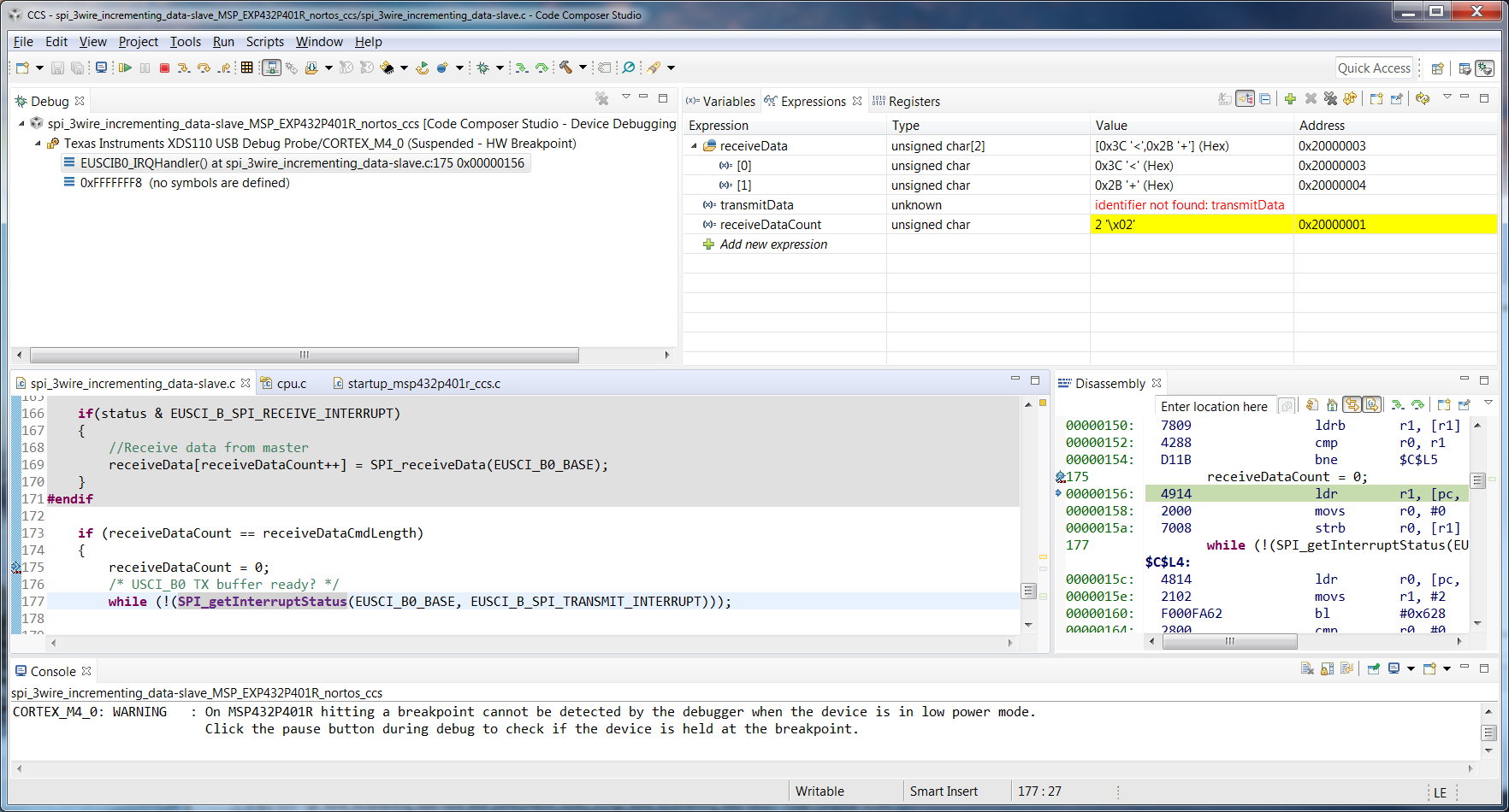
I tried working with some example code from each.  Upon startup, the SPI master sends the sequence 0x5678 to the slave.  It seems I get the initial 0x56, but not the 0x78 (in fact the code does not seem to enter the ISR, though the master seems to think it is sending it.

Here is the MSP432 slave code (using Code Composer Studio):

-------------

/* --COPYRIGHT--,BSD
 * Copyright (c) 2017, Texas Instruments Incorporated
 * All rights reserved.
 *
 * Redistribution and use in source and binary forms, with or without
 * modification, are permitted provided that the following conditions
 * are met:
 *
 * *  Redistributions of source code must retain the above copyright
 *    notice, this list of conditions and the following disclaimer.
 *
 * *  Redistributions in binary form must reproduce the above copyright
 *    notice, this list of conditions and the following disclaimer in the
 *    documentation and/or other materials provided with the distribution.
 *
 * *  Neither the name of Texas Instruments Incorporated nor the names of
 *    its contributors may be used to endorse or promote products derived
 *    from this software without specific prior written permission.
 *
 * THIS SOFTWARE IS PROVIDED BY THE COPYRIGHT HOLDERS AND CONTRIBUTORS "AS IS"
 * AND ANY EXPRESS OR IMPLIED WARRANTIES, INCLUDING, BUT NOT LIMITED TO,
 * THE IMPLIED WARRANTIES OF MERCHANTABILITY AND FITNESS FOR A PARTICULAR
 * PURPOSE ARE DISCLAIMED. IN NO EVENT SHALL THE COPYRIGHT OWNER OR
 * CONTRIBUTORS BE LIABLE FOR ANY DIRECT, INDIRECT, INCIDENTAL, SPECIAL,
 * EXEMPLARY, OR CONSEQUENTIAL DAMAGES (INCLUDING, BUT NOT LIMITED TO,
 * PROCUREMENT OF SUBSTITUTE GOODS OR SERVICES; LOSS OF USE, DATA, OR PROFITS;
 * OR BUSINESS INTERRUPTION) HOWEVER CAUSED AND ON ANY THEORY OF LIABILITY,
 * WHETHER IN CONTRACT, STRICT LIABILITY, OR TORT (INCLUDING NEGLIGENCE OR
 * OTHERWISE) ARISING IN ANY WAY OUT OF THE USE OF THIS SOFTWARE,
 * EVEN IF ADVISED OF THE POSSIBILITY OF SUCH DAMAGE.
 * --/COPYRIGHT--*/
/*******************************************************************************
 * MSP432 SPI - 3-wire Slave Incremented Data
 *
 * SPI slave talks to SPI master using 3-wire mode. Data is received
 * from master and data from slave is then transmitted back to master.
 * USCI RX ISR is used to handle communication, CPU normally in LPM0.
 * Prior to initial data exchange, master pulses slaves RST for complete
 * reset.
 *
 * Note that in this example, EUSCIB0 is used for the SPI port. If the user
 * wants to use EUSCIA for SPI operation, they are able to with the same APIs
 * with the EUSCI_AX parameters.
 *
 * Use with the master version of the code example
 *
 *                MSP432P401
 *              -----------------
 *             |                 |
 *             |                 |
 *             |                 |
 *             |             P1.6|<- Data In (UCB0SIMO)
 *             |                 |
 *             |             P1.7|-> Data Out (UCB0SOMI)
 *             |                 |
 *             |             P1.5|<- Serial Clock In (UCB0CLK)
 *
*******************************************************************************/
/* DriverLib Includes */
#include <ti/devices/msp432p4xx/driverlib/driverlib.h>

/* Statics */
//static volatile uint8_t transmitData = 0x01, receiveData = 0x00;
static volatile uint8_t transmitData = 0x01;
static volatile uint8_t receiveData[2] = {0,0};
static volatile uint8_t receiveDataCount = 0x00;
static volatile uint8_t receiveDataCmdLength = 0x02;
static volatile uint16_t receiveDataCmd = 0x5678;

/* SPI Slave Configuration Parameter */
const eUSCI_SPI_SlaveConfig spiSlaveConfig =
{
        EUSCI_B_SPI_MSB_FIRST,                          // MSB First
        EUSCI_B_SPI_PHASE_DATA_CHANGED_ONFIRST_CAPTURED_ON_NEXT,  // Phase
        EUSCI_B_SPI_CLOCKPOLARITY_INACTIVITY_LOW,     // Normal Polarity
        EUSCI_B_SPI_3PIN                               // 3wire mode
};

int main(void)
{
    /* Stop watchdog timer */
    WDT_A_holdTimer();

    /* Selecting P1.5 P1.6 and P1.7 in SPI mode */
    GPIO_setAsPeripheralModuleFunctionInputPin(GPIO_PORT_P1,
            GPIO_PIN5 | GPIO_PIN6 | GPIO_PIN7, GPIO_PRIMARY_MODULE_FUNCTION);

    /* Initialize slave to MSB first, inactive high clock polarity and
     * 3 wire SPI */
    SPI_initSlave(EUSCI_B0_BASE, &spiSlaveConfig);

    /* Enable the SPI module */
    SPI_enableModule(EUSCI_B0_BASE);

    /* Enable Receive interrupt */
    SPI_enableInterrupt(EUSCI_B0_BASE, EUSCI_B_SPI_RECEIVE_INTERRUPT);
    Interrupt_enableSleepOnIsrExit();
    Interrupt_enableInterrupt(INT_EUSCIB0);

    Interrupt_enableMaster();
    PCM_gotoLPM0();

}

//******************************************************************************
//
//This is the EUSCI_B0 interrupt vector service routine.
//
//******************************************************************************
void EUSCIB0_IRQHandler(void)
{
    uint32_t status;

    status = SPI_getEnabledInterruptStatus(EUSCI_B0_BASE);
    SPI_clearInterruptFlag(EUSCI_B0_BASE, status);

    if(status & EUSCI_B_SPI_RECEIVE_INTERRUPT)
    {
        //Receive data from master
        receiveData[receiveDataCount++] = SPI_receiveData(EUSCI_B0_BASE);
    }

    if (receiveDataCount == receiveDataCmdLength)
    {
        receiveDataCount = 0;
    }
}

-------------

  • Hi Medhi,

    The code looks OK. Have you tried to set a breakpoint into the SPI interrupt handler to see if you really do not get there.
    You also say that you only see the first byte received - how have you checked that?

    Regards,
    Stefan
  • Hi Stefan,

    Yes, I have set up a breakpoint in the SPI interrupt handler.  I see that the first byte goes into the SPI hardware RxBuffer and also gets loaded into my receive buffer.  However, the SPI interrupt does not seem to be entered again.

    I am waiting on receiving a logic analyzer to probe the traces to see if there is any insight there.

    Best,

    Mehdi

  • Hi Mehdi,

    OK, so that means that the communication looks OK and it is ensured that the characters arrive at the MSP432 ISR.
    Once you have received the first character and now continue to execute the code (RUN) -> Can you now reset the Master device so that it starts to send the data again. We should ensure that the Master really sends out the data. If you now get again an interrupt in the MSP432 this means that it does receive another character and the issue is more on the master side.
    There is still another option to think about - just to ensure. If you set a breakpoint in the MSP432 and the Master sends the data you only will see the last character int he RXBUF from the USCI module as the Master does not stop while the Slave does stop due to the breakpoint. But as mentioned in this case we should see the last character in the RXBUF and not the first.

    Regards,
    Stefan
  • > the SPI master sends the sequence 0x5678 to the slave.

    How is SPICR1:DFF set in the Master? The USCI doesn't know about 16-bit frames, and would instead see two bytes in rapid succession.

    My suspicion is that your slave is being overrun, though in that case you'd see the second byte (0x78?) in RXBUF.

    [Edit: In the absence of a scope, try slowing your SPI clock Way Way down.]

  • So I have attached a screenshot of the SPI communication.  It seems that both 0x78 and 0x56 do get sent by the master.  The protocol is to send the MSB first.

    I run the setup as follows:

    1. I start the IDE in debugging mode for the STM32
    2. I start CCS Studio IDE for the MSP432
    3. I continuously run both boards through the IDE
    4. I set a breakpoint on the master after sending the initial command bytes
    5. I set a breakpoint in the MSP432 in the SPI receive interrupt
    6. The SPI communication does not initiate until I press a pushbutton.  When I do so, I see the attached traces on my logic analyzer.  In the CCS IDE, I only seem to receive 0x56 but not 0x78 even though the logic analyzer shows that this was sent.

  • This is useful, since it shows that the 0x56 is sent second, which lines up the symptoms.

    Your slave is being overrun. The trace shows about 7usec between the bytes. Your MSP432 (MCLK) is running at about 3MHz, so that's 21 clocks, not nearly enough to execute that ISR.

    I suggest you speed up the slave clock (MCLK).
  • Thanks for the suggestion Bruce.  How high would I need to increase the clock?  I tried the following (I put this piece of code, and am still running into the same error:

    --------

    /* Setting DCO to 12MHz */
        CS_setDCOCenteredFrequency(CS_DCO_FREQUENCY_12);

    --------

    I also tried increasing to 24 MHz, and then even 48 MHz.  Am I increasing the DCO improperly?

  • I would have guessed that 12MHz (84 clocks) would be enough. That also looks like the right way to set it, though I should probably defer to the Driverlib wizards. What does CS_getMCLK() tell you?

    Are you still breakpointing in the (slave-side) ISR?
  • I put this code on a Launchpad, and drove it with an FR2311 master which sent 1 byte with 8MHz SPI clock every 7usec. I added something to wiggle P1.0 in the ISR.

    At 3MHz, my scope measured 132us; at 12MHz 21us; at 24MHz 10us, still too long. (Keep in mind I wasn't measuring the ISR entry/exit.) Optimization had no visible effect, meaning most of the time was spent in the library functions.

    I replaced the ISR with this, and at 12MHz the scope measured 3.4us; at 24MHz 2us. I didn't see overruns at 24MHz. The results at 12MHz were ambiguous. (You should try it with your test case.)

    void EUSCIB0_IRQHandler(void)
    {
        uint32_t status;
    
        P1OUT |= BIT0;
    #if 1
        if (EUSCI_B0->IFG & EUSCI_B_IFG_RXIFG0)
        {
            receiveData[receiveDataCount++] = EUSCI_B0->RXBUF;
        }
    
    #else
        status = SPI_getEnabledInterruptStatus(EUSCI_B0_BASE);
        SPI_clearInterruptFlag(EUSCI_B0_BASE, status);
    
        if(status & EUSCI_B_SPI_RECEIVE_INTERRUPT)
        {
            //Receive data from master
            receiveData[receiveDataCount++] = SPI_receiveData(EUSCI_B0_BASE);
        }
    #endif
    
        if (receiveDataCount == receiveDataCmdLength)
        {
            receiveDataCount = 0;
        }
        P1OUT &= ~BIT0;
    }
    

  • So interestingly, this did work.  I put a breakpoint on the "receiveDataCount = 0" line.  So my question is why doesn't the sample provided by TI work?  Is it that the main clock of the master SPI device is too fast for the original ISR as provided by TI?

    Do you think this has anything to do with low power modes?

    Actually, running this multiple times. I notice that sometimes the MSP432 does not receive the bytes properly.  For example, look at the screenshot:

  • I'm supposing(?) that you started with spi_3wire_incrementing_data.

    In that, the master side transmits from an ISR which has a structure similar to that in the slave, and probably has a similar run time. I suspect this introduces inter-byte pauses that allow both ends time to run.

    LPM0 is a fairly light sleep, and enterLPM0() is not much more than a WFI. I don't suspect LPMs being a problem here.

    [Edit: DMA can speed up the flow, though it may or may not fit well with your protocol.]

  • "I'm supposing(?) that you started with spi_3wire_incrementing_data. "

    So I'm not sure exactly what you mean by this.

    Regarding the SPI master device, it is actually an STM32F4 Discovery board, where I am running an SPI master example.  The master does not initiate SPI communication until I press a button on the board.  I make sure both codes are running before doing this.


    Yeah, I tried temporarily removing the LPM0 line and did not see a difference in behavior.

    Any insight as to why I do not always get the same behavior (refer to the screenshot in my previous post). Sometimes I get 0x56 and 0x78, but other times these become 0x2B and 0x3C.

    Could this have to do with improper reads as a result of clock speeds?

    So I just noticed this message on my console:

    CORTEX_M4_0: Flash Programmer: Reading device TLV failed.
    CORTEX_M4_0: Error initializing flash programming: Your XMS432P401R material is no longer supported. We recommend you moving to production-quality MSP432P401R/M silicon by ordering samples at www.ti.com/product/MSP432P401R.

  • Ah, I see your earlier post has changed since I first saw it.
    -------------
    It looks as though the bits are being shifted sometimes. The "usual suspects" here are
    (1) wires are too long, so the propagation delay is on the edge (of course this matters more at high-ish speed)
    (2) the SPI configurations don't agree, but it works most of the time. In particular, the settings for clock phase are defined differently at the two ends: if the STM32 CPHA=0, the MSP432 UCCKPH=1.
    -------------
    I thought you asked why the TI examples Do work, but didn't say which examples, so I guessed. Which TI examples don't work?
    -------------
    You may be able to clear that programming error by power cycling, but every time I've seen it I've had to do a Factory Reset, described in the Launchpad User Guide (SLAU597b) Sec. 5. It's a bother but only takes a couple of minutes (once I find the directions). I've encountered it mostly when I've made a mistake configuring the clock.
  • Hi Bruce,

    Thank you for your reply. It actually could be my setup and noise being picked up by wires, so I will try to clean that up and see if that improves the reliability.

    Regarding my statement on the TI example not working, I was referring to the fact that even running at 24 MHz using their 3 wire SPI slave example code with the status variable, that did not work while your edit did work. I would think that these examples were tested and proven to work (at least from MSP432 master to MSP432 slave). I was just curious as to why I was having problems using their example but now from a different SPI master device.

    So forgive me for my ignorance as I am relatively new to MSP432 and CCS (I come from a background of MSP430 and IAR Embedded Workbench). So I am somewhat new to syntax and the IDE.

    I want to ensure that my thought process is correct, so I am laying it out here.

    Here is the protocol of SPI communication between master and slave.

    1. Master sends 0x56 + 0x78 to slave.
    2. Slave receives these bytes, and sends acknowledgement bytes of 0xD5 +0xE5 back to master.
    3. Master, upon receiving the correct ACK bytes, sends a data stream of 0x0A + 0x0B + 0x0C + 0x0D to slave. This corresponds to a master write sequence.
    4. The master then sends a command for a master read sequence which is: 0x12 + 0x34
    5. The slave then sends ACK bytes of 0xD5 + 0xE5.
    6. The slave then sends the data stream of 0x55 + 0xAA + 0x55 + 0xAA.

    The program on the master side is already implemented as an example code project. I would like to implement the SPI slave device code using the MSP432 launchpad.

    Here are my thoughts:

    - There should be some kind of state variable to indicate where we are in the communication. Perhaps three states: Initialization, Receive data stream from master, Read sequence. The state variable should be initialized to the Initialization state.
    - There should be an array that tells how many bytes should be TXed or RXed based on the state.
    - For efficiency the MSP432 should use the SPI TX interrupt capability. This should work as follows. Let's say upon reading the initial 0x56 + 0x78 initialization bytes, the MSP432 should:
    -- Disable the RX interrupt
    -- Check to see if the SPI TX buffer is empty, and if so, send the first acknowledgement bytes, Increment the TX count variable
    -- Enable the SPI TX Interrupt
    -- After entering the ISR again, the MSP432 should check all ISR flags within an if block. It should enter the part of the code for the TX interrupt, check the TX buffer, send out the next acknowledgement byte, and increment the TX counter. Now it should check if the TX counter has reached the maximum. It should and at this point should change the state, enable the RX interrupt, disable the TX interrupt, and be ready to receive the four bytes.

    In the SPI interrupt, the if statement hierarchy was set up such that the RX interrupt flag is checked first, and then the TX interrupt flag is checked afterward.

    Is this general approach correct? Is there a better implementation?


    I was trying to implement this, but was having an issue with the TX/RX interrupts. So let's go to the point where the MSP432 receives the second (and last) initialization byte. I disabled the RX interrupt and enabled the TX interrupt. When the code entered the SPI interrupt again, though the receive interrupt enable bit was low, the receive interrupt flag was high, so it entered the receive interrupt part of the If branch.

    Was this a mistake in my general approach? Should I have reset the RX interrupt flag after disabling the interrupt enable bit? If so, how would I do that (again, I am relatively new to CCS).

    Best,

    Mehdi
  • I'm not really in a position to help you design your program, but it sounds like you have an idea what you want to do. I think the lesson is to keep things very lean and measure (e.g. with that logic analyzer) regularly.

    Doing a software-based SPI slave is a challenge on any MCU, since the master is going to want to communicate as fast as possible but the slave has things to do.

    I offered a piece of replacement code purely to try to measure where the time was going. It was based on the observation that (1) (only) RXIE was set and (2) reading RXBUF clears RXIFG. If you want the code to do something different, you should adapt it to your needs.
  • Hi Bruce,

    Thanks for your reply.  I'll be a little more specific about the problem I ran into.  So after receiving the 0x56 and 0x78 initialization bytes, I set the slave MSP432 to transfer the first acknowledgement byte back to the master, disable the RX interrupt, enable the transmit interrupt.  I can see that the interrupt enable register correspond to this: the IE for RX is 0, the IE for TX is 1.  However, the next time my code enters the interrupt, the code enters the if condition for the RX interrupt, because the RXIFG is set high (in fact upon inspection it was high when I disabled the interrupt enable bit).

    Here is the code:

    -----------

    /* --COPYRIGHT--,BSD
     * Copyright (c) 2017, Texas Instruments Incorporated
     * All rights reserved.
     *
     * Redistribution and use in source and binary forms, with or without
     * modification, are permitted provided that the following conditions
     * are met:
     *
     * *  Redistributions of source code must retain the above copyright
     *    notice, this list of conditions and the following disclaimer.
     *
     * *  Redistributions in binary form must reproduce the above copyright
     *    notice, this list of conditions and the following disclaimer in the
     *    documentation and/or other materials provided with the distribution.
     *
     * *  Neither the name of Texas Instruments Incorporated nor the names of
     *    its contributors may be used to endorse or promote products derived
     *    from this software without specific prior written permission.
     *
     * THIS SOFTWARE IS PROVIDED BY THE COPYRIGHT HOLDERS AND CONTRIBUTORS "AS IS"
     * AND ANY EXPRESS OR IMPLIED WARRANTIES, INCLUDING, BUT NOT LIMITED TO,
     * THE IMPLIED WARRANTIES OF MERCHANTABILITY AND FITNESS FOR A PARTICULAR
     * PURPOSE ARE DISCLAIMED. IN NO EVENT SHALL THE COPYRIGHT OWNER OR
     * CONTRIBUTORS BE LIABLE FOR ANY DIRECT, INDIRECT, INCIDENTAL, SPECIAL,
     * EXEMPLARY, OR CONSEQUENTIAL DAMAGES (INCLUDING, BUT NOT LIMITED TO,
     * PROCUREMENT OF SUBSTITUTE GOODS OR SERVICES; LOSS OF USE, DATA, OR PROFITS;
     * OR BUSINESS INTERRUPTION) HOWEVER CAUSED AND ON ANY THEORY OF LIABILITY,
     * WHETHER IN CONTRACT, STRICT LIABILITY, OR TORT (INCLUDING NEGLIGENCE OR
     * OTHERWISE) ARISING IN ANY WAY OUT OF THE USE OF THIS SOFTWARE,
     * EVEN IF ADVISED OF THE POSSIBILITY OF SUCH DAMAGE.
     * --/COPYRIGHT--*/
    /*******************************************************************************
     * MSP432 SPI - 3-wire Slave Incremented Data
     *
     * SPI slave talks to SPI master using 3-wire mode. Data is received
     * from master and data from slave is then transmitted back to master.
     * USCI RX ISR is used to handle communication, CPU normally in LPM0.
     * Prior to initial data exchange, master pulses slaves RST for complete
     * reset.
     *
     * Note that in this example, EUSCIB0 is used for the SPI port. If the user
     * wants to use EUSCIA for SPI operation, they are able to with the same APIs
     * with the EUSCI_AX parameters.
     *
     * Use with the master version of the code example
     *
     *                MSP432P401
     *              -----------------
     *             |                 |
     *             |                 |
     *             |                 |
     *             |             P1.6|<- Data In (UCB0SIMO)
     *             |                 |
     *             |             P1.7|-> Data Out (UCB0SOMI)
     *             |                 |
     *             |             P1.5|<- Serial Clock In (UCB0CLK)
     *
    *******************************************************************************/
    /* DriverLib Includes */
    #include <ti/devices/msp432p4xx/driverlib/driverlib.h>
    #define RECEIVE 0
    #define TRANSMIT 1
    
    /* Statics */
    //static volatile uint8_t transmitData = 0x01, receiveData = 0x00;
    static volatile uint8_t state = RECEIVE;
    static volatile uint8_t transmitDataCount = 0x00;
    static volatile uint8_t transmitDataInit[2] = {0xD5,0xE5};
    static volatile uint8_t receiveData[2] = {0,0};
    static volatile uint8_t receiveDataCount = 0x00;
    static volatile uint8_t receiveDataCmdLength = 0x02;
    static volatile uint16_t receiveDataCmd = 0x5678;
    
    /* SPI Slave Configuration Parameter */
    const eUSCI_SPI_SlaveConfig spiSlaveConfig =
    {
            EUSCI_B_SPI_MSB_FIRST,                          // MSB First
            EUSCI_B_SPI_PHASE_DATA_CHANGED_ONFIRST_CAPTURED_ON_NEXT,  // Phase
            EUSCI_B_SPI_CLOCKPOLARITY_INACTIVITY_LOW,     // Normal Polarity
            EUSCI_B_SPI_3PIN                               // 3wire mode
    };
    
    int main(void)
    {
        /* Stop watchdog timer */
        WDT_A_holdTimer();
    
        /* Setting DCO to 24MHz */
        CS_setDCOCenteredFrequency(CS_DCO_FREQUENCY_24);
    
        /* Selecting P1.5 P1.6 and P1.7 in SPI mode */
        GPIO_setAsPeripheralModuleFunctionInputPin(GPIO_PORT_P1,
                GPIO_PIN5 | GPIO_PIN6 | GPIO_PIN7, GPIO_PRIMARY_MODULE_FUNCTION);
    
        /* Initialize slave to MSB first, inactive high clock polarity and
         * 3 wire SPI */
        SPI_initSlave(EUSCI_B0_BASE, &spiSlaveConfig);
    
        /* Enable the SPI module */
        SPI_enableModule(EUSCI_B0_BASE);
    
        /* Enable Receive interrupt */
        SPI_enableInterrupt(EUSCI_B0_BASE, EUSCI_B_SPI_RECEIVE_INTERRUPT);
        /* Disable Transmit interrupt */
        SPI_disableInterrupt(EUSCI_B0_BASE, EUSCI_B_SPI_TRANSMIT_INTERRUPT);
        Interrupt_enableSleepOnIsrExit();
        Interrupt_enableInterrupt(INT_EUSCIB0);
    
        Interrupt_enableMaster();
        PCM_gotoLPM0();
    
    }
    
    void EUSCIB0_IRQHandler(void)
    {
        uint32_t status;
    
        P1OUT |= BIT0;
    #if 1
    
    
        if (EUSCI_B0->IFG & EUSCI_B_IFG_RXIFG0)
        {
            receiveData[receiveDataCount++] = EUSCI_B0->RXBUF;
        }
        else if(EUSCI_B0->IFG & EUSCI_B_IFG_TXIFG0)
        {
            /* USCI_B0 TX buffer ready? */
            while (!(SPI_getInterruptStatus(EUSCI_B0_BASE, EUSCI_B_SPI_TRANSMIT_INTERRUPT)));
    
            // Transmit data to master
            SPI_transmitData(EUSCI_B0_BASE, transmitDataInit[transmitDataCount]);
            transmitDataCount++;
            if (transmitDataCount >= 2)
            {
                transmitDataCount = 0;
                SPI_disableInterrupt(EUSCI_B0_BASE, EUSCI_B_SPI_TRANSMIT_INTERRUPT);    // Disable Transmit interrupt
                SPI_enableInterrupt(EUSCI_B0_BASE, EUSCI_B_SPI_RECEIVE_INTERRUPT);      // Enable Receive Interrupt
            }
        }
    
    #else
        status = SPI_getEnabledInterruptStatus(EUSCI_B0_BASE);
        SPI_clearInterruptFlag(EUSCI_B0_BASE, status);
    
        if(status & EUSCI_B_SPI_RECEIVE_INTERRUPT)
        {
            //Receive data from master
            receiveData[receiveDataCount++] = SPI_receiveData(EUSCI_B0_BASE);
        }
    #endif
    
        if (receiveDataCount == receiveDataCmdLength)
        {
            receiveDataCount = 0;
            // USCI_B0 TX buffer ready?
            while (!(SPI_getInterruptStatus(EUSCI_B0_BASE, EUSCI_B_SPI_TRANSMIT_INTERRUPT)));
    
            // Transmit data to master
            SPI_transmitData(EUSCI_B0_BASE, transmitDataInit[transmitDataCount]);
            transmitDataCount++;
    
            // Enable Transmit interrupt
            SPI_enableInterrupt(EUSCI_B0_BASE, EUSCI_B_SPI_TRANSMIT_INTERRUPT);
    
            // Disable Receive interrupt
            SPI_disableInterrupt(EUSCI_B0_BASE, EUSCI_B_SPI_RECEIVE_INTERRUPT);
    
        }
        P1OUT &= ~BIT0;
    }


    -----------

    So a few questions:

    1. Why was the RX IFG still high?
    2. Should I set this bit low when disabling the interrupt enable, or is the fact that it's high a sign that there is something going on?

    As a point of reference, I set a breakpoint on the master code after sending the acknowledgement bytes, preventing it from transmitting anything on the MOSI line.

    Best,

    Mehdi

  • The RXIFG is set independent of whether the RXIE is set. The RXIE just says whether a CPU (NVIC) interrupt happens. RXIFG (and TXIFG) is set for every byte in the transaction, even if you (the human) view any particular byte as "transmitted" or "received".

    A simple answer to your immediate question is to mimic the original code and work with only the enabled IFGs, which is pretty cheap:
    > status = EUSCI_B0->IFG & EUSCI_B0->IE; // Enabled interrupt flags
    > if (status & EUSCI_B_IFG_RXIFG) // Received?

    More generally: TXIFG/RXIFG remain set until you do something with them. The TXIFG behaves intuitively with turning the TXIE off and on, but the RXIFG is prone to becoming stale. This is complicated by the asynchronous (as seen by the slave) nature of the SPI. It might be possible to design the protocol so that you can always just clear RXIFG when you set RXIE. My first temptation would be to leave the RXIE on all the time and just (read and) throw away RXBUF if I'm not interested in it, just to keep track of the RXIFGs.

    Unsolicited: In
    > else if(EUSCI_B0->IFG & EUSCI_B_IFG_TXIFG0)
    [...]
    > while (!(SPI_getInterruptStatus(EUSCI_B0_BASE, EUSCI_B_SPI_TRANSMIT_INTERRUPT)));
    The while() is completely superfluous, since that's what the if() just tested.

    Even more generally: You're introducing new library calls into this ISR, when the library calls were (apparently) what was slowing it down before. I didn't dig into why those calls were (relatively) expensive -- part of it may simply be thrashing the Flash read buffer with all the branching. You should be measuring regularly to see how much all this is costing.

    Unsolicited: Keep in mind that a "volatile" variable must be read/written to memory whenever it's referenced. Usually you can ease that by caching it in a local variable. In this program -- where main() never does anything after startup -- I would say none of those variables needs to be "volatile".
  • Hi Mehdi,

    have you been able to solve the problem with all the great inputs from Bruce.
    If solved, please select "Resolved" for the post that solved your issue so this thread can be closed out. If you have a different question, please select "Ask a related question" or " Ask a new question".
    Thanks a lot!

    Best regards,
    Stefan

**Attention** This is a public forum