


Other Parts Discussed in Thread: EVM430-I2040S
Hello everyone,
This question came up recently, so I wanted to provide some guidance in case others had the same question. Currently, EMDC supports AC RMS and peak measurements. While we don't explicitly list that DC measurements are supported by EMDC v1.30.00, it's possible with just a few minor changes in the EMDC GUI. For this exercise, we'll use the EVM430-i2040S development board, since it supports both AC and DC measurements. For the maximum DC voltage and current, let's assume they are equal to 200V and 10A.
Assuming you've downloaded and installed EMDC v1.30.00, open the EMDC GUI and then open the pre-configured EMDC example project, "EVM430-i2040S_SH_1V_1C_50Hz".
Update sensor parameters
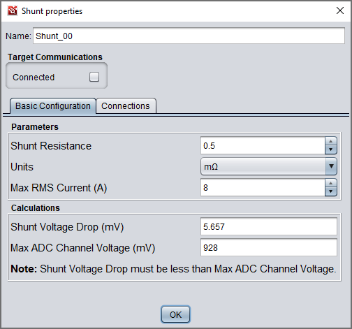
First, we'll need to adjust the voltage and current sensor parameters in the EMDC GUI, since they have been implemented for RMS inputs and are automatically converted to peak units for easily comparing the sensor output voltage with the maximum ADC input voltage. However, our DC values already have peak units, so we'll need to convert from peak to RMS units by multiplying the DC values by the square root of 2. Conceptually, a RMS DC value doesn't make sense, but remember we're doing this to offset the automatic conversion between units. This ensures that EMDC selects the correct GAIN settings for absolute maximum inputs.
Convert DC voltage to "RMS".
200V DC --> 200 / sqrt(2) = 141.421V = ~142V (RMS)
Convert DC current to "RMS".
10A DC --> 10 / sqrt(2) = 7.071A = ~8A (RMS)
Enter these "RMS" values into the voltage and current sensor parameter windows in EMDC. Notice the current sensor here is a shunt. This is because current transformers and rogowski coils cannot measure DC current.

Update library configuration
Next, modify the microcontroller's library configuration inside the controller's property window in EMDC. Starting with the "Results" tab, click the "Deselect All" button, and then manually select the following results:
- VRMS (use this result for the DC voltage measurement)
- IRMS (use this result for the DC current measurement)
- Active Power
- Active Energy
The other parameters don't apply to DC measurements. Click the "Save" button before continuing.
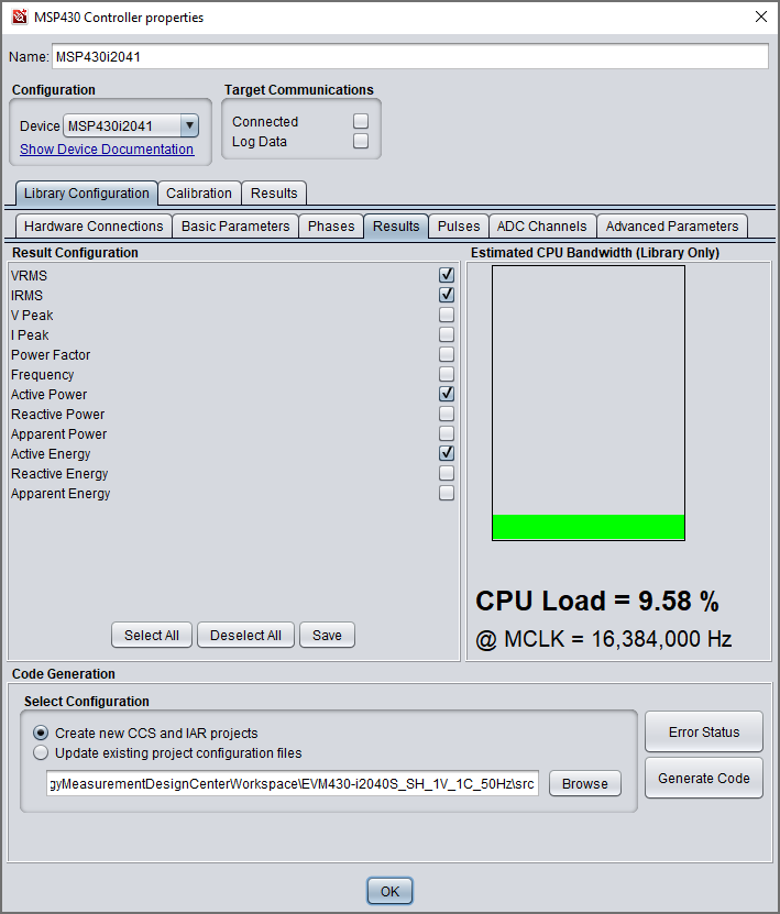
Next, under the "ADC Channels" tab, disable the DC filters for all ADC channels by deselecting them.

Check for errors, generate the code and program the target microcontroller. You can find detailed instructions on how to do this in the EMDC Technology Guide.
Perform system calibration for DC measurements
Assuming you've soldered on the wires for the high voltage DC connections and made the isolated EMDC communication connections (described here in the EMDC Technology Guide), configure your high voltage DC test source to provide the DC voltage and current desired for calibration, such as 200V and 1A.
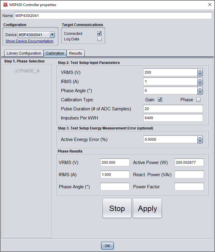
Next, open the microcontroller's properties window and navigate to the "Calibration" tab. Then, select your phase(s). Here, it's "PHASE_A". Most importantly, we'll only need to perform GAIN calibration for DC measurements, so click "Gain" under "Step 2". For VRMS, enter the DC voltage, 200V. For IRMS, enter the DC current, 1A. Keep "Phase Angle" equal to zero. Click "Start" and then "Apply" to complete calibration. In the pop-up window, click "Yes" to save the calibration factors to Flash memory or click "No" to keep them in RAM. More details about the overall calibration process can be found in the EMDC Technology Guide.
View the DC measurements
In the microcontroller's properties window, click the "Results" tab to view the measurements. Again, remember that we're using VRMS and IRMS values for DC voltage and current respectively. Also, the other results are blank because we didn't select them during the library configuration.

Conclusion
That's it! We're planning to integrate this functionality into a future EMDC release to make everything easier, but in the meantime, these instructions should help you use EMDC to measure DC. If you have any questions or feedback, please feel free to comment below. After a few days, the thread will lock, so you can ask your question in a new thread. Thanks!