This thread has been locked.

If you have a related question, please click the "Ask a related question" button in the top right corner. The newly created question will be automatically linked to this question.

MSP430G2230: Unable to program this device using MSP-FET and Spy Bi-Wire (2 Wire JTAG)

Part Number: MSP430G2230
Other Parts Discussed in Thread: MSP-FET

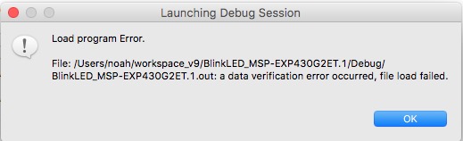
OK, so we have assembled this device the right way round but we are failing to communicate with it!

We have been trying to programme it using CCS via MSP-FET and Spy Bi-Wire (2 Wire JTAG).  We can't even get the most basic communications going.  It doesn't respond to "Identify" and the "Test Connection" button is greyed out.

Is there anyone around who could give us a little guidance on getting started?  For instance, in Target Configurations is "TI MSP430 USB1 [Default]" the correct Connection setting?

Thanks!

  • Hello,

    I suspect that your JTAG circuitry doesn't match our recommended circuitry. Please refer to the following resources.

    Regards,

    James

  • Hi James

    We have implemented Fig 2-2 exactly and are relying on CCS and the MSP-FET to provide appropriate voltages and timings. We have shortened the ribbon cable to about 3 inches. Can't think what else to do.

    Tomorrow, when I get some suitable wire jumpers, we'll try running the MSP-FET on a LaunchPad Kit to see if it works there. That LaunchPad Kit works properly stand-alone with CCS and this laptop, so we should be able to verify the MSP-FET on it.

    All suggestions welcome!
  • Sounds like a good plan. Perhaps the board isn't powered up or it's requiring more power than the MSP-FET can provide. For connecting to the LaunchPad, you can remove the ribbon cable from the MSP-FET and connect the jumper cables directly to the pins on the MSP-FET. Refer to the helpful pin layout diagram on the bottom of the MSP-FET. Keep in mind that "VCC_TOOL" supplies VCC while "VCC_TARGET" senses VCC that's provided from another source for level-setting the signals. Hope this helps.

    Regards,

    James
  • Hi James

    I tested the MSP-FET on our LaunchPad board with just 4 wires -- Vcc (VCC-TOOL), Vss, SBWTDIO and SBWTCK. It loaded and ran without a problem.  Conclusion: the MSP-FET is working fine.

    I went back and retested our minimally populated board and I still get a failure to load (see attached).  By the way, the software is just a modified version of one of the example projects, adapted for our setup.  We haven't started verifying it since it doesn't even load, let alone run!

    I am attaching an extract from our schematic.  The only components on the test board are U1 (the MCU), C7 and C10 (power decoupling), R7 and C6 (RST decoupling) and R12 (SBWTCK protection).  To avoid any possible interference, no other components have been assembled. Only 4 wires are connected between the board and the MSP-FET -- Vcc (VCC-TOOL), Vss, SBWTDIO and SBWTCK -- and they are in a ribbon cable about 3 inches long.  We have checked end to end for continuity and shorts.

    In case it helps diagnosis, after CCS hangs we see "1" (~Vcc) on pins 6 and 7 of the MCU -- i.e. both SBW pins are high.

    Is it possible that the JTAG fuse has blown somehow? Can the CSS detect that or is there any other way to do so?  Would that give the same effect -- "file load failed"?

    Just casting around for any ideas . . .

    Thanks

    Noah

  • Hi James
    So I finally noticed a line in the Console reporting a Data Verification error:
    "MSP430: File Loader: Verification failed: Values at address 0xC000 do not match Please verify target memory and memory map."
    Having read a bit more about Linker Command Files, I got suspicious about some of the files that had carried over from the example project we used as the starting point. I went back to the beginning and did a clean start project, copied some code into main.c and, hey presto, it works!!
    Thanks for giving us your time and attention.
    Regards
    Noah

**Attention** This is a public forum