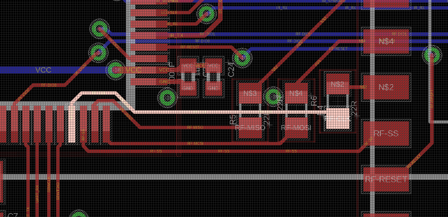
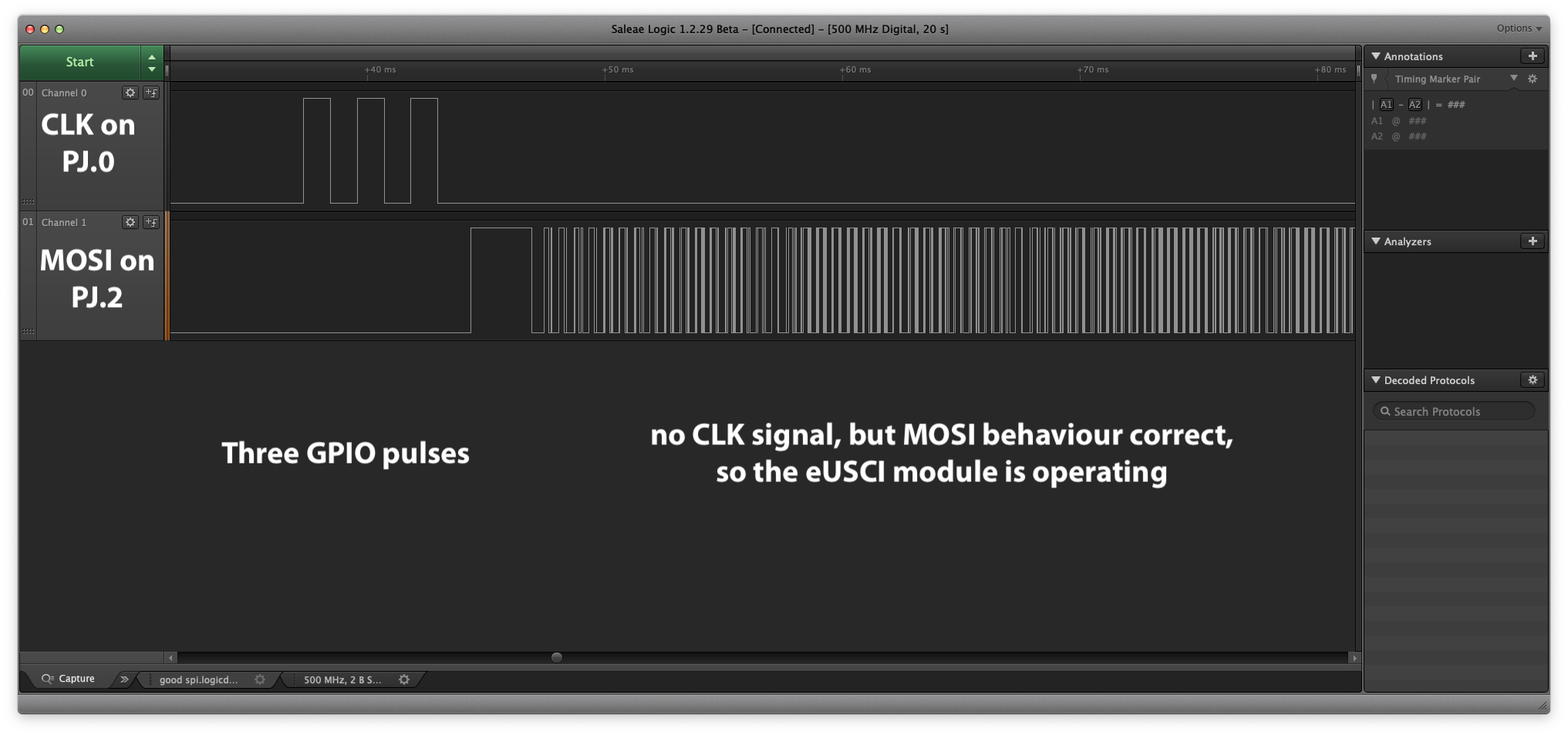
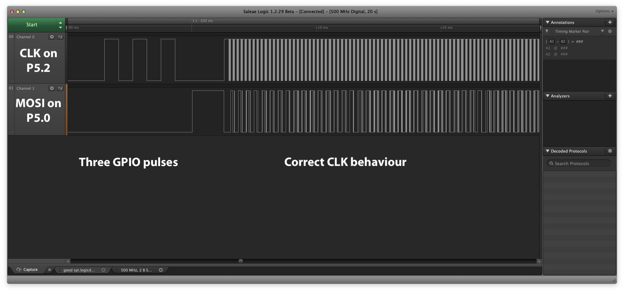
I am having an issue with the SPI functionality on the MSP430FR6043 when trying to map it to port PJ (pins PJ.0-PJ.3). The MOSI signal on PJ.2 works fine, but the clock does not appear on PJ.0 at all. When mapped to port P5 (P5.0 - P5.3) everything works as expected. I double check the electrical connection by setting the PJ.0 as a digital IO and sending out some pulses, which registered on the scope correctly. I repeated this test on three separate devices, with the same results. I tried both with an SPI device connected, and with the MCU pin floating. I don't think the pins on port PJ are entering JTAG mode, the SYSJTAGPIN is 0, and the device behaves the same when debugging with SPW, as well as when running off battery with the SPW programmer disconnected and the RESET pin pulled high at all times. Could there be something else preventing the PJ.0 pin from muxing into the SPI clock on the UCA2 module? Please advice. I would really appreciate having these pins specifically available for that feature, as I am working with a very tight PCB layout, and the position of the USS module and the LCD is fixed, leaving me very little wiggle room.
Attached: scope trace from pin P5.2 (working) and PJ.0 (not working), and the test code I ran. The tests were performed on a custom PCB, with either the PJ.0 pin floating (connected only to a scope probe), or connected to an SPI slave device thought a 22R resistor. Debugged with an MSP FET, over a SBW connection with only the SBWCLK and SBWTDO pins connected. Thanks for any input!
#include "driverlib.h"
uint8_t RXData = 0;
uint8_t TXData = 0;
int i=0;
void main(void){
//Stop watchdog timer
WDT_A_hold(WDT_A_BASE);
PMM_unlockLPM5();
//Set DCO frequency to max DCO setting
CS_setDCOFreq(CS_DCORSEL_0, CS_DCOFSEL_3);
CS_initClockSignal(CS_SMCLK, CS_DCOCLK_SELECT, CS_CLOCK_DIVIDER_1);
//test CLK pins in output mode
GPIO_setAsOutputPin(GPIO_PORT_PJ,BIT0);
GPIO_setAsOutputPin(GPIO_PORT_P5,BIT2);
//3 pulses
for(i=0; i<6; i++){
GPIO_toggleOutputOnPin(GPIO_PORT_PJ, BIT0);
GPIO_toggleOutputOnPin(GPIO_PORT_P5, BIT2);
__delay_cycles(1000);
}
//for PORT PJ (with CLK not working)
GPIO_setAsPeripheralModuleFunctionInputPin(GPIO_PORT_PJ, BIT0 | BIT1 | BIT2 | BIT3, GPIO_PRIMARY_MODULE_FUNCTION);
//for PORT P5 (working fine)
GPIO_setAsPeripheralModuleFunctionInputPin(GPIO_PORT_P5, BIT0 | BIT1 | BIT2 | BIT3, GPIO_SECONDARY_MODULE_FUNCTION);
//Initialize Master
EUSCI_A_SPI_initMasterParam param = {0};
param.selectClockSource = EUSCI_A_SPI_CLOCKSOURCE_SMCLK;
param.clockSourceFrequency = CS_getSMCLK();
param.desiredSpiClock = 50000;
param.msbFirst = EUSCI_A_SPI_MSB_FIRST;
param.clockPhase = EUSCI_A_SPI_PHASE_DATA_CHANGED_ONFIRST_CAPTURED_ON_NEXT;
param.clockPolarity = EUSCI_A_SPI_CLOCKPOLARITY_INACTIVITY_HIGH;
param.spiMode = EUSCI_A_SPI_3PIN;
EUSCI_A_SPI_initMaster(EUSCI_A2_BASE, ¶m);
//Enable SPI module
EUSCI_A_SPI_enable(EUSCI_A2_BASE);
EUSCI_A_SPI_clearInterrupt(EUSCI_A2_BASE,EUSCI_A_SPI_RECEIVE_INTERRUPT);
// Enable USCI_A0 RX interrupt
EUSCI_A_SPI_enableInterrupt(EUSCI_A2_BASE,EUSCI_A_SPI_RECEIVE_INTERRUPT);
//Wait for slave to initialize
__delay_cycles(100);
TXData = 0x1; // Holds TX data
//USCI_A0 TX buffer ready?
while (!EUSCI_A_SPI_getInterruptStatus(EUSCI_A2_BASE, EUSCI_A_SPI_TRANSMIT_INTERRUPT)) ;
//Transmit Data to slave
EUSCI_A_SPI_transmitData(EUSCI_A2_BASE, TXData);
__bis_SR_register(LPM0_bits + GIE); // CPU off, enable interrupts
__no_operation(); // Remain in LPM0
}
#pragma vector=USCI_A2_VECTOR
__interrupt
void USCI_A2_ISR(void){
switch(__even_in_range(UCA2IV, USCI_SPI_UCTXIFG))
{
case USCI_SPI_UCRXIFG: // UCRXIFG
//USCI_A0 TX buffer ready?
while (!EUSCI_A_SPI_getInterruptStatus(EUSCI_A2_BASE,EUSCI_A_SPI_TRANSMIT_INTERRUPT));
RXData = EUSCI_A_SPI_receiveData(EUSCI_A2_BASE);
//Increment data
TXData++;
//Send next value
EUSCI_A_SPI_transmitData(EUSCI_A2_BASE,TXData);
//Delay between transmissions for slave to process information
__delay_cycles(40);
break;
default:
break;
}
}