This thread has been locked.

If you have a related question, please click the "Ask a related question" button in the top right corner. The newly created question will be automatically linked to this question.

MSP430L092: Its characteristics and booster circuis

Part Number: MSP430L092

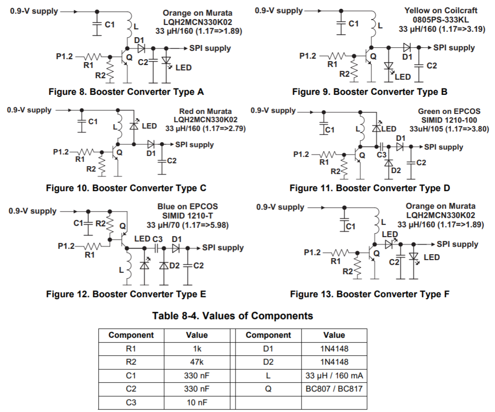
Refferring to SLAA472, MSP430L092 Development Guide (Figure 8), and SLAU321 (Figure 13) etc, a L092 hardware board is developed. Except for the abnormal replacement of LED with 1N4148, the basic work is stable. But the following problems are not clear:

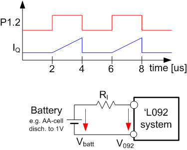
1, The working voltage can not reach 0.9V. Near 1v, the LED began to display download intermittently.

2, When working voltage is 1.3v, it works normally. But the current measured by the ammeter raeches 0.15mA and at that time the LED flashes continuously and quickly, I wonder why . When we work,  the power supply to be contained by load, so we also will meet this flashing and can not work normally.

keeping forward to hearing from your answer.

  • Hello,

    - on SLAA472, Fig.8  Here the LED is supposed to serve two purposes; first a visual feedback ...  second act as a low cost "zener-diode"  or in other words to limit the supply voltage of the SPI memory to about ~3.2V.

    The device  'L092 operates down to 0.9V.  The launch voltage however is higher...

    When you rise the voltage let's say from 0.8V to 1.5V you can observe that somewhere at 1.1V the device draws current and starts operation. This is when the brownout reset is released. This voltage is V(BOR_IT+)  defined in SLAS673   Page 28.  After the 'L092 started it can then safely operate down to 0.9V .

    What you might have observed was a BOR-Storm near to the brownout release voltage on a weak(resistive) supply voltage.

    Have a nice day

  • Hi Johann,

    Thank you for your replay. I did the experiment again. At 1.22V,  show slow brightness and extinction of LED due to the internal resistance of power supply. At 1.24V,  there will be no such situation, so your analysis is correct.

    Now there is a ploblem that our power supply will be generated by a certain frequency rectifier. For example, the rectifier load is composed of 50k and 0.1uF in parallal. At this time, even if the measured DC voltage is 1.3V, LED just flickers continuously and quickly. I wonder what to do about this. Is there a way to isolate the effect of this internal resistance? I used a chip that didn't seem to have that effect. Thank you for your continued support.

    Regards,

    Ruan

  • Hello Ruan,

    If your impedance of the power supply is 50kOhms and the output voltage is buffered with 0.1uF... and your voltage over the cap is 1.3V; then you've got the following situation:

    - The time constant for charge/discharge tau=R*C  is 5ms with the given values.

    - The intended blink rate of the LED is approximately 1Hz; this translates into 500ms on-time and 500ms off-time.

    - With an assumed load into the transistor of 1mA to drive the LED.

    ==>  The 0.1uF cap is discharged within a couple of milliseconds after the L092 tries to turn on the charge pump.

    Therefore I believe that you see some hysteretic dim flickering on the LED.

    Idea: try to attach a AA or AAA cell as supply to see if there is a generic problem.

    In case I misunderstood your setup then please send me a circuit diagram as base for further discussion.

    "Pictures and drawings with named components allow a more precise explanation of observations and proposals"

    have a nice day

         Johann

  • Hi Johann,

    Yes, using battery power, it doesn't seem so seriousl. Even so, at V=1.22V, it  also shows flicking of about 2s period. However, if rectifier power supply is used, it must include rectifier and filter. For half-wave rectifier, tau= Rl*C>3-5T filter circuit is needed. In our circuit, 10kHz (T=.1ms) pulse signal generated after rectifier is used as power supply for  EEPROM etc,  so c=.1uf  plus device equivalent resistance Rl=20k, Rl*C=2ms=20T is used as filter,  this circuit  works normally. For save power supply , let it go  into your boost circuit, not into EEPROM directly, everything happened.

    I have no idea about why the blink rate of the LED is approximately 1Hz as tau=5ms and the principles of generating  the  hysteretic dim flickering  and how to avoid it.

    Regards,

    Ruan

  • Don't know why I  couldn't send circuit figures here?

  • Hi Ruan; I'll try to assume one scenario an calculate a typical case for you here; then you would just need to transpose that to your application.  ...

  • Hi Ruan,

    below an example calculation....

    I took the boost circuit diagrams from the L092's User's guide.

    In this example we take the converter "Type A" . We further assume to have a supply voltage of 1V (maybe from an partly discharged AA battery). Fig 8 says that the input voltage was 1.17V ant the output was 1.89V. Here the LED was is used as voltage limiter. We know that LEDs of different colors have different operation voltages. The voltage of 1.89V would here be orange (we know even if it does not say); red would be a lower voltage, blue a higher. In our case we take a green one that operates at around 3.2V . The other components we take as given in the list.

    The 'L092 blink pulses are generates as a train of pulses at ~250kHz. With the charge pump circuits this appears as blinking of the LED. The pulses on P1.2 would look line the red curve above. The output voltage on P1.2 from time=2us to 4us will turn the transistor on. Since the transistor in not perfect, a small voltage of ~150mV between collector and emitter is lost. The remaining voltage across the 33uH coil L is smaller. At t=2us current starts to flow through inductor and transistor and increases in an linear way. The unit of inductance is Henry[H] which is [Vs/A].   with L=V*t/I. we can calculate the current through the transistor at the t=4us.  I_L=V_L*t_on/L;   =>  I_L4us=0.85[V]*2e-6[s]/33e-6[Vs/A];   =>  51.5mA. This is the peak current at time =4us. The average current is a fourth of it, here 12.87mA.

    In the blue curve the current through the transistor is shown. This is the same for the coil while the transistor is on. Calculating the current through the LED is simple by applying the "energy conservation law". The output voltage at the coil is the LED voltage plus the D1 voltage. We assume for an 1N4148 about 600mV to be conservative for this case. With P_in=V_in*I_in_avg and P_out=V_out*I_out and P_in=P_out and V_out=V_LED + V_D1;    =>  I_out=V_in*I_in_avg/(V_LED+V_D1)   =>  I_out= 0.85[V]*12.87e-3[A]/(3.2[V]+0.6[V])=2.88mA.  In other words our charge pump is good to supply 2.88mA at 3.2V. This current has to be shared between the LED and the SPI memory chip. Here it is more than we need. If you would like to lower the power budget, simply increase the inductance of L and recalculate (either as shown or with TINA-Spice).

    Now, we could see that the max current of the system is 51.5mA. Our 'L092 system is being supplied via a battery as shown in the small circuit above. R_I is the impedance of the battery (all electrical wiring we assume have no remarkable impact here).  The voltage V_092 needs to be above 0.9V to avoid a reset.

    This allows a max voltage drop across the R_I of 0.1V.  With U_R_I = R_I*I_L4us;   =>  R_I=0.1[V]/51.5e-3[A]=1.94 Ohms.

    A supply impedance larger than 1.94Ohms leads to problems with the given conditions since the supply voltage on the 'L092 goes below 0.9V. A practical save value would be at about 1 Ohms since we did just some simple approximation and have not considered wiring resistance and the parasitic inductivity in supply.

    Typical AA batteries would have impedance characteristics as shown below... 

    AA cells are therefore good enough; the same is true for AAA and AAAA and some, but not all, coin cells. 

    just transpose the shown technique to your application and it will work

       best regards    

            Johann

  • Thank you very much for your detailed reply, which has provided me with a thorough understanding of the operating mechanism. There are also two final questions to ask:

    1, Generally, it is difficult to get the curve of the internal resistance vs DOD for rectifier+filter power supply (I measured a good rectified supply, the internal resistance is about 2ohm), and don’t know how to affect the internal resistance. Can we say that your solution is mainly for battery?

    2, I don’t know what is the Iohmin=-1mA and Iolmin=2.5mA listed in your SLAS673,p24 table. I measured the total current of my circuit is 130uA (only P1.1 output), but this can’t be correct, as the internal resistance of the ammeter can’t make the booster circuit work, and how to solve it.

    Regards,

    Ruan

  • A1; yes you are right... to get the discharge curves you would need to ask the battery manufacturers; they will call you and ask what for, but in general it is no secret. In worst case you can measure it yourself. And yes you are right again the original target application was for AA, AAA, AAAA batteries. Meanwhile many applications run on two solar cells in series (no clue what size, but they have a large cap in ||).

    A2; typical amp-meters use a ADC that requires 200mV drop across a shunt resistor for full scale. Loosing 200mV on a 12V system is no deal. It might be still ok when you measure on an 3.3V system. Measuring on an 1.8V system is causing definitely problems. Here we are talking 0.9V . If your current range is 2mA the meter's internal shunt gas 100Ohms. The shunt contributes to the Ri from the earlier calculations. Here you would need an compensating amp meter. Those come depending on the frequency range for 1000+ $.   In other words you might have measured an artifact.

**Attention** This is a public forum