


Part Number: MSP430F5328
Hello,
We are using an MSP430F5328 processor on one of out boards and are experiencing an interesting issue. The basic process is to use a PWM timer to periodically (every 2 mSecs) turn on an amplifier for a specific amount of time (200-300 uSecs). Shortly after turning the amp on (90-150 uSecs) we generate an interrupt to process some data. We are using TA0 for this. The PWM output is on P1.4, so we are using TA0.3 for this. And we are using TA0.2 to generate our interrupt. The basic code is below:
|
This all works fine when using an IAR emulator. The timing is shown below:
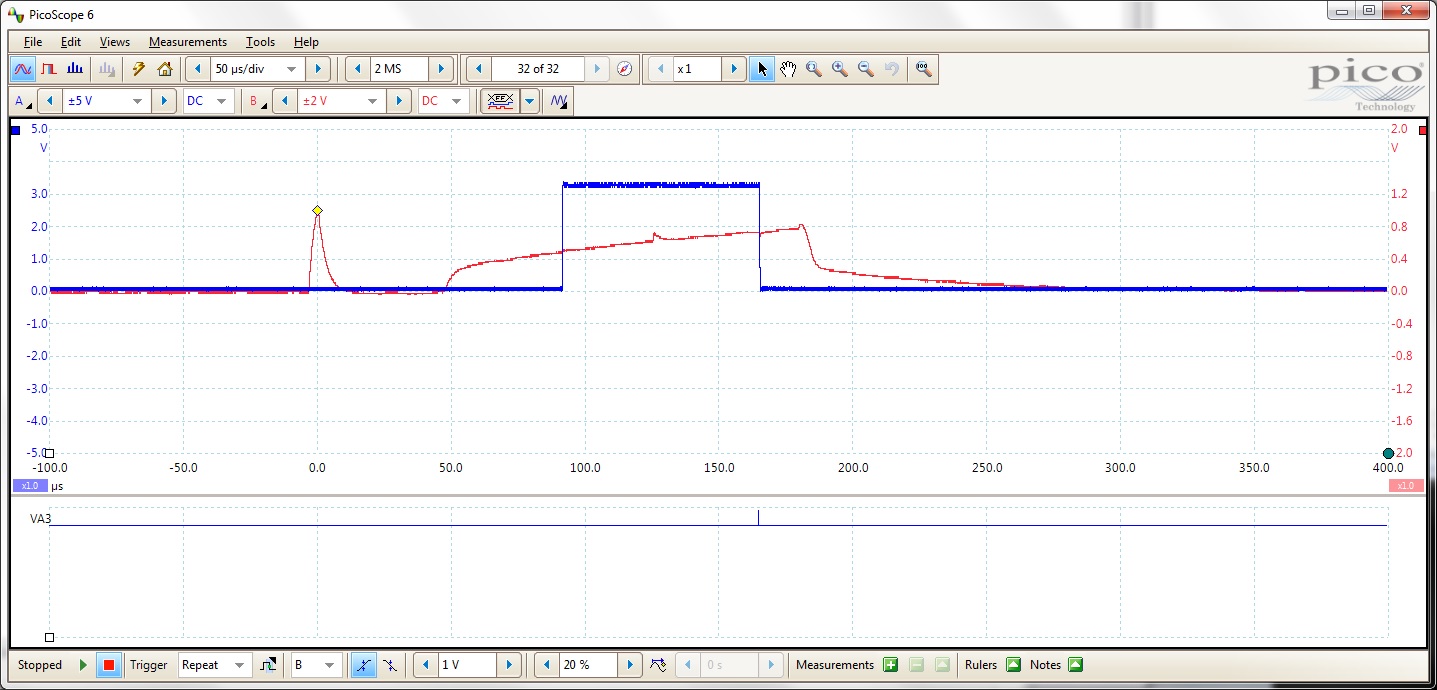
The RED line is the amplifier output which starts at the start of the timer cycle. As can be seen, the power to the amp is cut off at 182 uSecs which is the designed time. The BLUE line rises when the timer generates an interrupt at 93 uSecs, again the designed time.
However, when running the board without the emulator, whereas the PWM timing stays the same, the timing of the interrupt is extended significantly as can be seen in the screenshot below (this is with the same code and timing parameters as before, but here the interrupt doesn't occur until 228 uSecs as shown below:

If we change the delay for the interrupt to the minimum count, which should be about 30 uSecs, we get the timing shown below:

With this timer count, we get the interrupt 168 uSecs into the clock cycle rather than the 30 uSecs we would have expected.
What could possibly be causing this issue with the interrupt generation? Using timer TA0.1 rather than TA9.2 for this made no difference.
Any help would be appreciated.
Robert Buchanan
