


Other Parts Discussed in Thread: MMWAVEICBOOST, , SYSCONFIG, IWR6843, IWR6843ISK
Hi,
I am trying to control the SOP pins on the mmwaveICBOOST using the MSP432E401Y MCU Launchpad, so I can directly go into functional and flashing modes without manually controlling the SOP jumper settings. To start with, I established a UART connection between launchpad and mmwaveICBOOST, which is working fine.
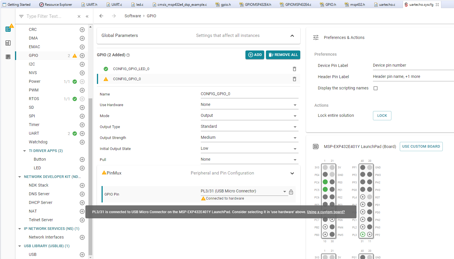
I looked into the schematics and the pins 15,17, and 19 on the J6 correspond to SOP0, SOP1, and SOP2 pins, respectively, which means if I want to control them using MSP432E4 launchpad then the corresponding GPIO pins on the launchpad are PL1, PL2, and PL3. When I tried to configure these three GPIO pins using sysconfig tool, it gives me the warning that ''these pins are also connected to mini-USB connector, so select it in 'Use hardware' field''. However, If I go to the 'Use Hardware' field, I only see user switches and launchpad LEDs there.
1). I am new to the sysconfig tool, is there a way we can change the default GPIO pins configurations?
2). Also, is this warning an issue if I configure the same pins (PL1-3) to control the IWR6843?
Anyways, I went ahead and sent the ON signal to PL3 to make the IWR6843ISK go into the functional mode. I verified that the signal is coming on these PL pins but when I remove all three jumpers OFF on the SOP pins of the mmwaveIC BOOST, and try to control the IWR6843 through these GPIO pins (PL1-3), the stored program (mmwave demo) on the IWR6843 does not run.
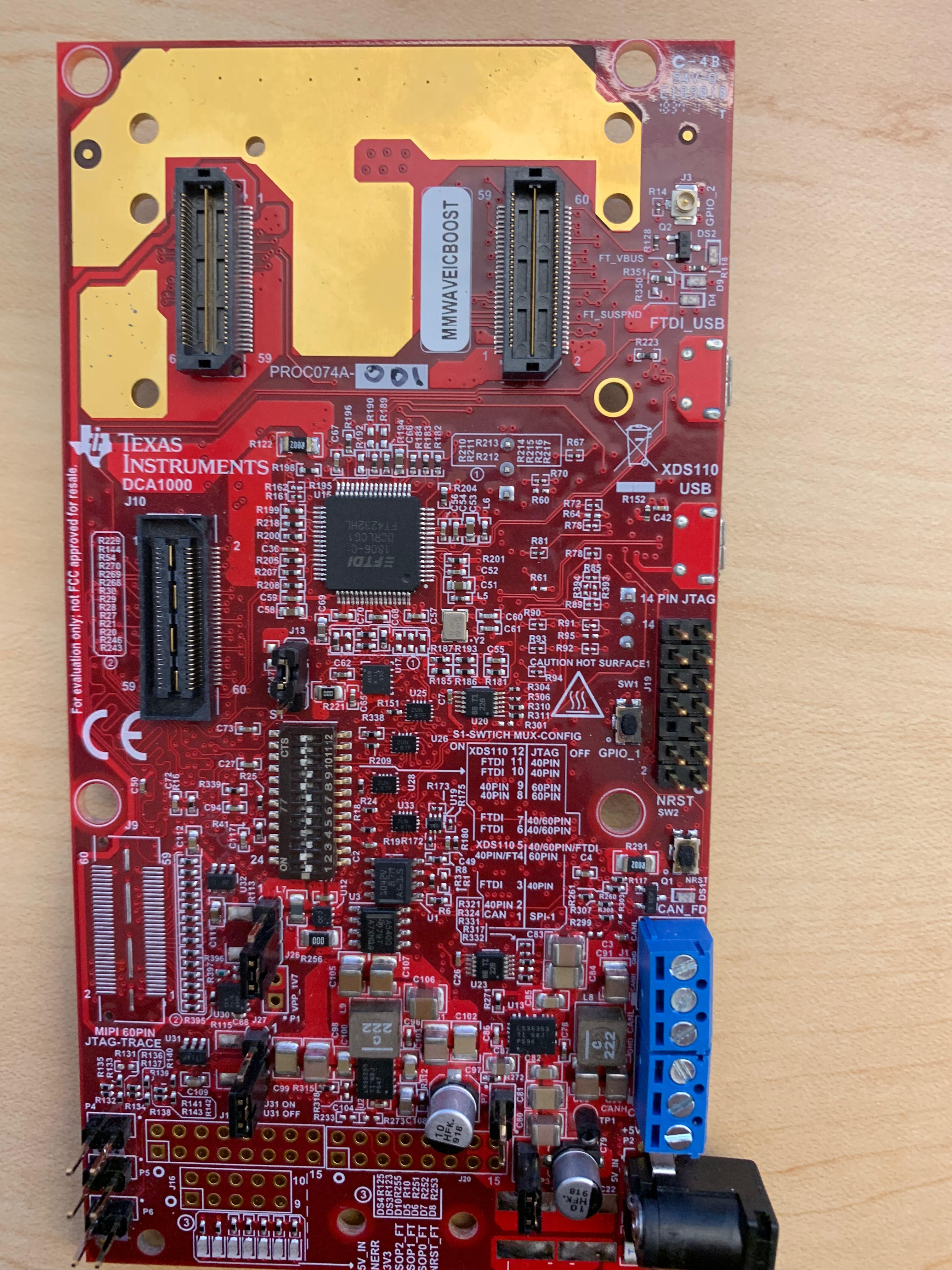
Please find the MUX settings on the switch (S1) to enable the 40 pin interface.
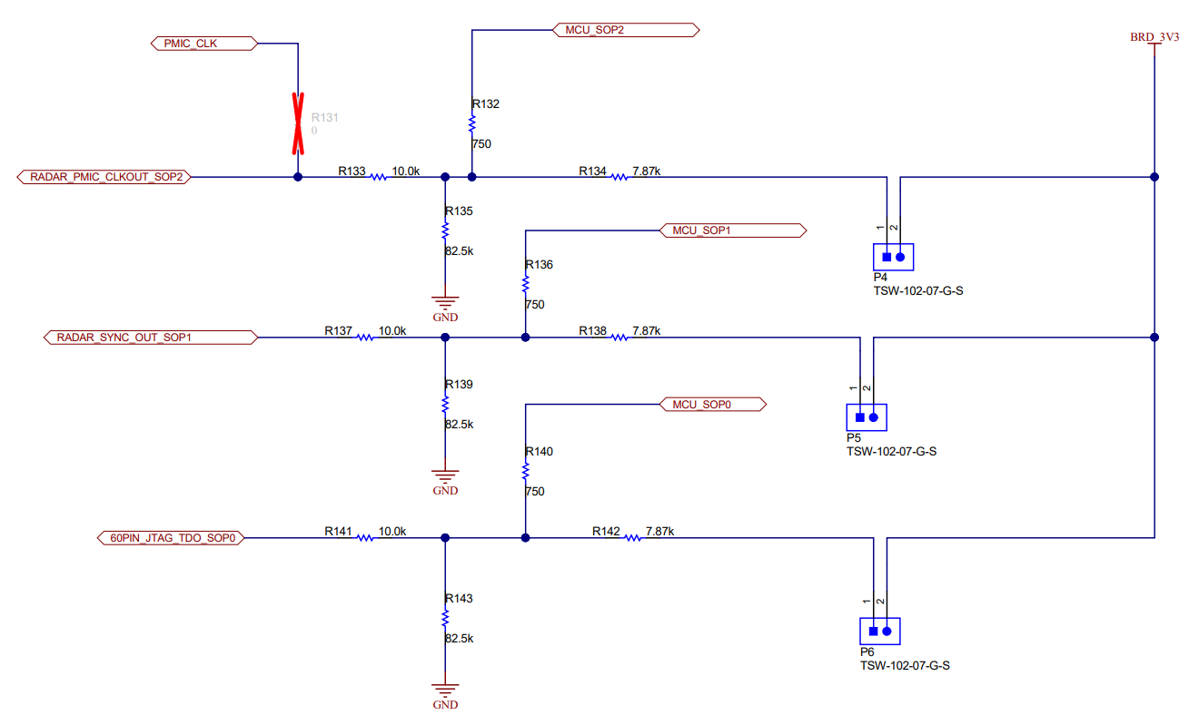
From this below schematics, I can see these MCU_SOP pins can bypass the the SOP jumper settings and it should work. Is there any hardware changes, we need to do (like changing resistor values) to make it work?
Thank you.

