


Part Number: MSP432P4111
G'Day all,
I posted on the forum earlier today regarding a way of detecting the start of a DMA based UART receive (here - getting GPIO interrupt off a pin setup as UART Rx). That first approach didn't work, so I'm looking at another.
The MSP432 eUSCI (UART mode) has a start bit interrupt that I thought might give me a way of detecting start of reception. Unfortunately I found documentation and actual operation confusing and I hoped you could clarify.
- Section 24.3.16 of SLAU356I says that the Tx interrupt and Rx interrupts must be off for DMA work but it doesn't say anything about the start bit interrupt so I assume that there will be no bad interaction between the DMA and the start bit interrupt. Is that true?
- Section 24.3.15.3 (the section about the UART) talks about UCSTTIFG being a "start BYTE" received interrupt, but the register descriptions (section 24.4.10 for the interrupt enables, section 24.4.11 for the flags) call UCSTTIE/UCSTTIFG a "start BIT" interrupt. Can you confirm which is the correct description? When should this interrupt fire?
- In the MSP432 Peripheral Driver Library Users guide (DriverLib users guide - can't find a web link, but it gets installed along with SimpleLink, e.g. hereC:/ti/simplelink_msp432p4_sdk_3_20_00_06/docs/driverlib/msp432p4xx/MSP432_DriverLib_Users_Guide-MSP432P4xx-4_30_01_01.pdf). The descriptions around the UART interrupts seem a bit confused. Compare the following sections
- 28.3.3.1 - UART_clearInterruptFlag(module, mask)
- description of mask -> points to EUSCI_A_UART_enableInterrupt()
- NOTE: This is not a correct API function name (but its close)
- 28.3.3.2 - UART_disableInterrupt(module, mask)
- description of mask ->Ored combination of
- EUSCI_A_UART_RECEIVE_INTERRUPT
- EUSCI_A_UART_TRANSMIT_INTERRUPT
- EUSCI_A_UART_RECEIVE_ERRONEOUSCHAR_INTERRUPT
- EUSCI_A_UART_BREAKCHAR_INTERRUPT
- NOTE: No mention of startbit or transmit compelete
- description of mask ->Ored combination of
- 28.3.3.4 - UART_enableInterrupt(module, mask)
- description of mask ->Ored combination of
- EUSCI_A_UART_RECEIVE_INTERRUPT
- EUSCI_A_UART_TRANSMIT_INTERRUPT
- EUSCI_A_UART_RECEIVE_ERRONEOUSCHAR_INTERRUPT
- EUSCI_A_UART_BREAKCHAR_INTERRUPT
- NOTE: No mention of startbit or transmit compelete
- description of mask ->Ored combination of
- 28.3.3.6 - UART_getEnabledInterruptStatus(module)
- description of return value -> ORed combination of
- EUSCI_A_UART_RECEIVE_INTERRUPT_FLAG
- EUSCI_A_UART_TRANSMIT_INTERRUPT_FLAG
- NOTE: Where did BreakChar and erronouschar go?
- NOTE: No mention of startbit or transmit compelete
- description of return value -> ORed combination of
- 28.3.3.7 - UART_getInterruptStatus(module, mask)
- description of mask value -> ORed combination of
- EUSCI_A_UART_RECEIVE_INTERRUPT_FLAG
- EUSCI_A_UART_TRANSMIT_INTERRUPT_FLAG
- EUSCI_A_STARTBIT_INTERRUPT_FLAG
- EUSCI_A_TRANSMIT_COMPLETE_INTERRUPT_FLAG
- NOTE: Only occasion in all interrupt control APIs where the startbit and transmit complete flags are mentioned.
- NOTE: Where did BreakChar and erronouschar go?
- description of return value -> ORed combination of
- EUSCI_A_UART_RECEIVE_INTERRUPT_FLAG
- EUSCI_A_UART_TRANSMIT_INTERRUPT_FLAG
- NOTE: Where did the startbit and transmit compete go?
- NOTE: Where did BreakChar and erronouschar go?
- NOTE: What is the difference between the values with _FLAG at the end, and those without? They seem to be used in mixed ways.
- description of mask value -> ORed combination of
Operation
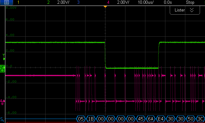
I've setup my system with a 2Mbaud UART (our use of DMA comes from the high speed of the UART) and a pin toggling whenever the "Start bit" interrupt fires. The data comes in bursts of 48 characters, so I'd expect 48 interrupts. That is not what I get. For each burst, I always seem to get the first toggle on the 3rd character and then after that I get a toggle every 5 or 6 characters, but sometimes it misses one. Its interesting that I get a toggle after the data burst completes.
My interrupt handler (HWI) looks like this
uint8_t intStatus_u8;
intStatus_u8 = MAP_UART_getInterruptStatus(EUSCI_A2_BASE, EUSCI_A_UART_STARTBIT_INTERRUPT_FLAG);
if (intStatus_u8 & EUSCI_A_UART_STARTBIT_INTERRUPT_FLAG)
{
MAP_UART_clearInterruptFlag(EUSCI_A2_BASE, EUSCI_A_UART_STARTBIT_INTERRUPT);
P4->OUT ^= GPIO_PIN3;
}

Looking in execution graph, we can explain some of the behvaiour.
- The missed toggles look like they might occur because another HWI ran. 0x20006640 is an unrelated timer interrupt has the same priority as the start bit interrupt. It is not clear why the start bit interrupt never ran.
- The failure to toggle on all characters might be due to the turnaround time in the interrupt handler.
- prior the first interrupt, the device is quiet - why didn't it hit the start bit of the first character (or at least the first character). Why doesn't the start bit interrupt ever trigger on the first character?

Cheers
Julian
