This thread has been locked.

If you have a related question, please click the "Ask a related question" button in the top right corner. The newly created question will be automatically linked to this question.

CCS/MSP430L092: CCS 9.3.0 under Windows 10 successfully programs MSP430L092 external SPI image using a MSP-FET430UIF, but not with a MSP-FET

Part Number: MSP430L092
Other Parts Discussed in Thread: MSP-FET, CCSTUDIO

Tool/software: Code Composer Studio

Was using CCS 9.3.0 under Windows 10 Pro to program a MSP430L092, with the target device in a MSP-TS430L092. This was done as part of seeing if the problem in the related thread of CCS under Ubuntu crashing could be repeated. With CCS 9.3.0 under Windows 10, CCS is not crashing but found that when using a MSP-FET the option to program the external SPI image doesn't work.

The software is:
- CCS 9.3.0.00012
- Debug Server 9.3.0.1863 com.ti.ccstudio.debugserver.win64.feature.group
- TI Emulators 8.4.0.00006 com.ti.emulation.pack.win64.feature.group
- Code Composer Studio IDE MSP430 Components 9.3.0.201912041800
- TI MSP430 tool-chain 9.2.1 com.ti.msp430.build_debug.feature.group

The attached program blinks the LEDs on the MSP-TS430L092. The Debug and Release configurations are set to different generate a different blink pattern:

- The Debug configuration has the LEDs on for 10% of the time.

- The Release configuration has the LEDs on for 90% of the time.

The sequence which shows the problem:

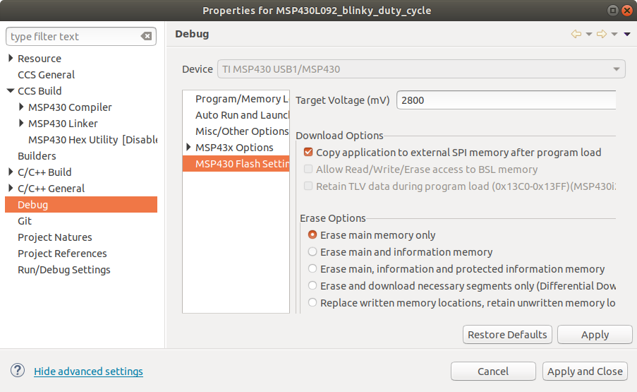
1. Compile the project for the Debug and Release configurations. In the project properties under Debug -> MSP430 Flash Settings check the "Copy application to external SPI memory after program load" option.

2. With the MSP-TS430L092 connected to a MSP-FET430UIF set the active configuration as Debug.

3. Download the program, set running and terminate the debug session. The LEDs flash with the expected 10% duty cycle.

4. Remove and then re-connect the USB to the MSP-FET430UIF. The MSP430L092 starts from the SPI image and the LEDs flash with the expected 10% duty cycle. I.e. with the MSP-FET430UIF successfully programmed the external SPI image.

5. With the MSP-TS430L092 connected to a MSP-FET430UIF set the active configuration as Release.

6. Download the program, set running and terminate the debug session. The LEDs flash with the expected 90% duty cycle.

7. Remove and then re-connect the USB to the MSP-FET430UIF. The MSP430L092 starts from the SPI image and the LEDs flash with the expected 90% duty cycle. I.e. with the MSP-FET430UIF successfully programmed the external SPI image.

8. Change the MSP-TS430L092 to be connected to MSP-FET and set the active configuration as Debug.

9. Download the program, set running and terminate the debug session. The LEDs flash with the expected 10% duty cycle.

10. Remove and then re-connect the USB to the MSP-FET. The LEDs show the "Error Blink" described in the MSP430L092 Loader Code SLAU324A, indicating the ROM bootloader has not detected a valid SPI image. I.e. with the MSP-FET the external SPI image has not been programmed successfully.

11. With the MSP-TS430L092 connected to a MSP-FET set the active configuration as Release.

12. Download the program, set running and terminate the debug session. The LEDs flash with the expected 90% duty cycle.

13. Remove and then re-connect the USB to the MSP-FET. The LEDs show the "Error Blink" described in the MSP430L092 Loader Code SLAU324A, indicating the ROM bootloader has not detected a valid SPI image. I.e. with the MSP-FET the external SPI image has not been programmed successfully.

The above sequence has been repeated a number of times.

MSP430L092_blinky_duty_cycle.zip

I have had a quick look at the MSP Debug Stack Open Source Package in slac460y and the DLL430_OldApiV3::writeToExternalMemory function in DLL430_v3\src\DLL430_OldApiV3.cpp calls "SpiGenerateImage(), Generate Program Image in SPI Memory Utility Function" in the MSP430L092 ROM so not sure why use of a MSP-FET430UIF works but a MSP-FET doesn't.

  • Hi Chester,

    Thank you to describe the problem so clearly.

    From your description the problem lies on the debugger. I will help you to find out the reason. 

    Eason

  • Hi Chester,

    Please wait for some time, I have consult the expert, but they are on vacation.

    Eason

  • Hi,

    About your problem, the problem may lies on the power supply.  Voltage generation of MSP-FET and MSP-FET UIF is complete different. Maybe you can try to change the output voltage or use a multimeter to test if it is in spec.

    Besides, I want to recreate your problem based on MSP-TS430L092. But for both MSP-FET and MSP-FETUIF, I all can't download the code into SPI EEPROM. I have chosen  "Copy application to external SPI memory after program load" option. Can you give me some advice.

    Eason

  • Eason Zhou said:
    Maybe you can try to change the output voltage or use a multimeter to test if it is in spec.

    In the project properties the output voltage for the VCC_TOOL output has been set to 2.8V:

    The Active Cable on the MSP-TS430L092 contains TLVH431IDBVR devices which drop the VCC_TOOL output by 1.24V, to form the VCC supply for the MSP430L092. With the above configuration the VCC measured on the MSP-TS430L092 Target Socket Module was:

    - 1.58V when using a MSP-FET

    - 1.65V when using a MSP-FET430UIF

    Both of these are within the allowed range in the MSP430L092 datasheet of 1.5 V to 1.65 V for operation at the fastest clock rarte of 4 MHz.

    Therefore, don't think the power supply is the problem.

  • Eason Zhou said:
    But for both MSP-FET and MSP-FETUIF, I all can't download the code into SPI EEPROM. I have chosen  "Copy application to external SPI memory after program load" option. Can you give me some advice.

    As shown on the above post I have "Copy application to external SPI memory after program load" option. The jumpers on the MSP-TS430L092 boards are:

    Target Socket Module : JP1, JP2 and JP3 fitted

    Active Cable Target Socket Module : JP1:1, JP1:2 and JP2 fitted

  • Hi Chester,

    Thank you for your reply. 

    First I need recreate your's issue. Please wait for some time.

    Eason

  • Hi Chester,

    I also ask my colleague to double check for me.

    We all meet the same problem that we can't download code into SPI memory using MSP-FET or MSP-FETUIF under CCS9.20, IAR7.12 and IAR5.51.

    As the device is too old, there isn't enough source to support. Since you can using MSP-FETUIF to download code into SPI memory, I think it will not affect your product development. I will close this thread. I am sorry.

    Eason

  • Hi,

    This is probably related to this other topic:

    Older debuggers work but now new MSP-FET (SN17xxxxxx and above).

    Regards,

    Alex.

  • Hi Alexander,

    Thank you for your help.

    As I checked, it is not a hardware issue. It seems lies on the software. 

    We can download code into RAM memory, but we can't download it into external spi memory. It seems that our debug tools chain doesn't support this function anymore. Besides, we can't find the setting on CCS or IAR according to this document: http://www.ti.com/lit/an/slaa472a/slaa472a.pdf. MSP430L092 is a really really old device. 

    Eason

**Attention** This is a public forum