This thread has been locked.

If you have a related question, please click the "Ask a related question" button in the top right corner. The newly created question will be automatically linked to this question.

CCS/MSP430F6638: MSP430F6638 pwm signal with timer

Part Number: MSP430F6638

Tool/software: Code Composer Studio

Hello,

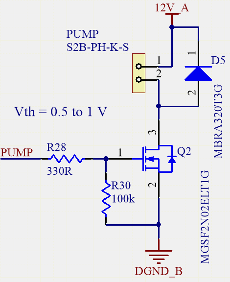
I am using the MSP430F6638 in my design. I have to command a motor by pwm and I am creating my pwm signal with timer. However I have a doubt about how to "send" in the program this pwm signal to the motor. I mean which command should I write so the motor start to work. In other words what is the command which from the moment I will write it, the motor will "immediately" start to turn ? Here is my code below.

void motor_ON(void){

P3SEL|=BIT1; //SELECT P3.1 AS TA1 and not I/O


TA1CTL = TASSEL_2 + TACLR+ MC_1; // SMCLK, up mode


TA1CCR0 = PWM_PERIOD-1; // counter value that defines the pwm period

TA1CCTL1 = OUTMOD_6; // toggle/set

TA1CCR1 = motor_DC;      // motor duty cycle
}

Is this enough or is still there something to enable so the motor could work ? In others words at which command the motor will "receive" the pwm signal and start working, and if this command is missing what should it be ? 

Same question, to stop the motor. What is the proper way to do it ? I thought about a solution but I'm not sure if it's correct. In order to put off the pwm signal and so stop the motor, I just changed the output mode from toggle and set to reset and put the shortest value (1) in the TA1CCR1 register so I will have a really short duty cycle and then as soon as the counter will reach the value "1" (which is really fast) the output of the timer will remain at 0 and then the motor will be stopped. I hope that it's clear. Here is the code below :

void motor_OFF(){

TA1CCTL1 = OUTMOD_5; // reset
TA1CCR1 = 1; // very short DC so the motor remains off quickly
}

So, to start and stop the motor are these the correct way to do it, or is something missing ? 

Thank you.

Best regards,

Mike


  • It would be useful for you to mention what kind of motor you have and how it's wired. If you're using a DC "hobby" motor and an L298N(-ish) H-bridge, this came up near the top of the Google list:

    https://howtomechatronics.com/tutorials/arduino/arduino-dc-motor-control-tutorial-l298n-pwm-h-bridge/

    In particular, you don't seem to be driving IN1 and IN2, which absence will probably prevent the motor from running.

    Also, you need to set P3.1 as an output ("P3DIR |= BIT1;") to get PWM out.

  • Hi,

    Can you post the schematic of your design? Differently motor need differently numbers of PWM.

    MSP430 can't drive a Motor directly. It need a MOSFET, Mosfet driver or something else to drive it.

    If it is a DC motor, you need a H bridge and at least 2 numbers of PWM.

    Eason

  • Hi Eason and Bruce,

    Yes I know MSP430 can't drive a motor directly. I used mosfet as a driver. It's not really a motor but an air pump (for blood pressure monitoring). Here is the scheme. 

    Considering this and the code I wrote in the last post, is this going to work ? I mean I am mainly talking about the code. As I said in the last post at which command the motor will "receive" the pwm signal and start working ? And is it correct to stop the pump as I mentioned it in the last post ? 

    Thank you.

    Regards,

    Mike

  • The motor will start to run (give or take some inertia) when the TA1.1 pin goes high, causing the FET to pass current to the motor. In a typical cycle, this will happen at the beginning of the period (set) and end at the CCR1 value (toggle->off).

    The order of your code will probably make the first cycle a bit odd. The timer starts counting as soon as you set MC=1. It will count-to-0 until you set CCR0, then it will count upwards. Depending on the value of motor_DC it may or may not have counted past  that value by the time you set CCR1. You may want to consider setting everything else before setting TA1CTL.

    I expect the OFF code will work, but it won't take effect until the end of the current PWM_PERIOD. If you really want it to stop immediately, you can do something like:

    > TA1CCTL1 = OUTMOD_0 | (0*OUT);  // Force TA1.1 to OUT=0 immediately

    i.e. set OUT=0 along with OUTMOD=0 to force that OUT value on the pin.

    Also, don't forget P3DIR.

  • Hi Bruce,

    "The motor will start to run (give or take some inertia) when the TA1.1 pin goes high, causing the FET to pass current to the motor. In a typical cycle, this will happen at the beginning of the period (set) and end at the CCR1 value (toggle->off). The order of your code will probably make the first cycle a bit odd. The timer starts counting as soon as you set MC=1. It will count-to-0 until you set CCR0, then it will count upwards. Depending on the value of motor_DC it may or may not have counted past  that value by the time you set CCR1. You may want to consider setting everything else before setting TA1CTL."

    Yes I know that it happens at the beginning of the period (set) and end at the CCR1 value. But I just want to know which line of the code will be responsable of the start of the pump. This is an important point so I could know in which order to write the different commands in the program so this specific line could be the last one written after the other timer settings commands. Let's say we want to create a function called pump_on() which will turn immediately the pump as soon as it will be called. So if I understood what you say this means that in the pump_on() function I will have one line which is TA1CTL = TASSEL_2 + TACLR+ MC_1; which will set the SMCLK as clock source and the up mode. Is this going to turn the pump on ? I mean is this the specific code line that will turn immediately the pump when it is called ? Or it's the one that set the output mode, or the one that set the duty cycle or ... ?

    Thank you.

    Regards,

    Mike

  • Maybe this is the missing piece: None of those statements causes TA1.1 to go high. The timer sets TA1.1  high.

    No, I'm not playing with words -- it's an important distinction. The timer counts, and checks for "EQUn" events in the process. You arrange for the events, but nothing will happen until the timer encounters them.

    In your sequence:

    1) Setting TA1CTL starts the timer counting, but it never gets past 0 (CCR0). There are no EQUn events since it doesn't "count to" anything.

    2) Setting CCR0>0 allows the timer to count up. When it reaches CCR0, there will be an EQU0 event (but no action).

    3) Setting CCTL1 sets actions for subsequent EQU0 and EQU1 events. Since CCR1==0, there will be no EQU1 event.

    4A) Setting CCR1 < whatever TA1R is when you set it will have no immediate effect ("missed it"). When it reaches CCR0, there will be an EQU0 event ("set"->high).

    4B) Setting CCR1 > whatever TA1R is when you set it will cause an EQU1 event when TA1R reaches CCR1 ("toggle" -> high).. When it reaches CCR0 there will be an EQU0 event ("set"->high).

    5) The next time TA1R reaches CCR1 (next cycle) there will be an EQU1 event ("toggle" ->low). I.e. the second and subsequent cycles will be what you expect.

    None of these things happens when you execute the statements in your code, only when the timer gets around to it. (Also: The timer ticks in parallel with the CPU, so figure on it increasing by 5-15 ticks during each statement.)

  • Hi Bruce,

    Thank you for your answer. I am using P3.1 of MSp430F6638 for the pwm period and the P3.2 pin is connected to the gate of the MOSFET that will drive the pump. So considering your last post here is the code I tried to implement.

    P3SEL|=BIT1;                                                     //SELECT P3.1 AS TA1 and not I/O
    P3DIR|=BIT1;                                                    //DEFINE P3.1 AS OUTPUT (COMPARE)
    TA1CCR0 = PWM_PERIOD-1;                        // counter value that defines the pwm period

    P3SEL|=BIT2;                                                 //SELECT P3.2 where the gate of the MOSFET is connected AS TA1 OUTPUT and not I/O
    P3DIR|=BIT2;                                                // Define P3.2 as output (compare)

    TA1CCTL1 = OUTMOD_6;                         // toggle/set mode
    TA1CCR1 = PUMP_DC;                            // counter value that defines the pwm duty cycle for the pump
    TA1CTL = TASSEL_2 + TACLR+ MC_1; // SMCLK, up mode

    As you said in one of your post, I set everything before the TA1CLT command. Is the code abov seem to be correct ? I'm not sure about it but with this configuration is the pump going to turn on at the last line code ? 

    PS : HERE is below the altium scheme.

    Thank you.

    Regards,

    Mike

  • This sequence will give you more predictable results, but TA1.1 still won't go high immediately, rather when the timer gets around to it. More generally, the first cycle will be odd-looking (inverted) since there's no EQU0 event when you first start the timer. (Going through the OUTMOD choices I'm not sure there's a better one for this.)

    Here's a suggestion that I think will (a) Pretty much eliminate your latency concerns and (b) Make the first cycle look "normal": Don't use TACLR, rather initialize TA1R=PWM_PERIOD-2. Once you start the timer, the first thing it will see is the EQU0 which will "set" TA1.1 high. The delay until the first event (which will in turn energize the motor) will be one timer tick, which (from the CPU's point of view) is immeasurably small.

  • Hi Bruce,

    Thank you very much for your answer. 

    "Here's a suggestion that I think will (a) Pretty much eliminate your latency concerns and (b) Make the first cycle look "normal": Don't use TACLR, rather initialize TA1R=PWM_PERIOD-2. Once you start the timer, the first thing it will see is the EQU0 which will "set" TA1.1 high. The delay until the first event (which will in turn energize the motor) will be one timer tick, which (from the CPU's point of view) is immeasurably small."


    In the code I have written I didn't even use the TACLR field of TAxCTL register. So according to your post I should in my code add TA1R=PWM_PERIOD-2 so the pump could turn "immedialtely" from the CPU's point of view. So taking my code this should look like this :

    P3SEL|=BIT1;                                                     //SELECT P3.1 AS TA1 and not I/O
    P3DIR|=BIT1;                                                    //DEFINE P3.1 AS OUTPUT (COMPARE)
    TA1CCR0 = PWM_PERIOD-1;                        // counter value that defines the pwm period

    P3SEL|=BIT2;                                                 //SELECT P3.2 where the gate of the MOSFET is connected AS TA1 OUTPUT and not I/O
    P3DIR|=BIT2;                                                // Define P3.2 as output (compare)

    TA1CCTL1 = OUTMOD_6;                         // toggle/set mode
    TA1CCR1 = PUMP_DC;                            // counter value that defines the pwm duty cycle for the pump

    TA1R = PWM_PERIOD-2;
    TA1CTL = TASSEL_2 + TACLR+ MC_1; // SMCLK, up mode

    It seems to be correct, now ? And just to be sure, we are talking about the toogle and set mode of the up mode, right ? 

    Thank you.

    Regards,

    Mike

  • Looks about right. You could also use OUTMOD=7 (Reset/Set) in this case.

  • Hi Bruce,

    So with all of that, if we want to make a function called pump_on to turn the pump on we should have something like this (below) 

    void pump_on()

    {

    P3SEL|=BIT1;                                                     //SELECT P3.1 AS TA1 and not I/O
    P3DIR|=BIT1;                                                    //DEFINE P3.1 AS OUTPUT (COMPARE)
    TA1CCR0 = PWM_PERIOD-1;                        // counter value that defines the pwm period

    P3SEL|=BIT2;                                                 //SELECT P3.2 where the gate of the MOSFET is connected AS TA1 OUTPUT and not I/O
    P3DIR|=BIT2;                                                // Define P3.2 as output (compare)

    TA1CCTL1 = OUTMOD_6;                         // toggle/set mode
    TA1CCR1 = PUMP_DC;                            // counter value that defines the pwm duty cycle for the pump

    TA1R = PWM_PERIOD-2;
    TA1CTL = TASSEL_2 + TACLR+ MC_1; // SMCLK, up mode

    }

    and then we could make a function pump_off to turn off the pump. This function could be like this (below)

    void pump_off()

    {

    TA1CCTL1 = OUTMOD_0 | (0*OUT);  // Force TA1.1 to OUT=0 immediately

    }

    It seems to be correct for you these two functions ? Is there any big mistake here ? 

    Thank you.

    Regards,

    Mike

  • Looks about right. What does it do when you run it?

    After you see it in action, you may find it useful to ramp up/down the speed rather than turning it on/off immediately. Some (mechanical) devices care about that more than others.

  • Hi Bruce,

    When I run the air pump it should inflate a cuff (blood pressure monitoring), and I am using the pwm signal to control it, that's why I was talking about pump_on and pump_off functions.

    Regards,

    Mike

  • Hi Bruce,

    Since I need several time in a while loop to turn on the pump (in other words I need the pump to keep inflating the cuff until we reach a certain pressure threshold, so I need in this while loop the pump ON until we reach the threshold and then we turn it off) ,which part of the pump_on function below should I remove and put in the main so it will be called once and which part (that is responsible of turning on the pump) should I keep in the pump_on function ? 

    void pump_on()

    {

    P3SEL|=BIT1;                                                     //SELECT P3.1 AS TA1 and not I/O
    P3DIR|=BIT1;                                                    //DEFINE P3.1 AS OUTPUT (COMPARE)
    TA1CCR0 = PWM_PERIOD-1;                        // counter value that defines the pwm period

    P3SEL|=BIT2;                                                 //SELECT P3.2 where the gate of the MOSFET is connected AS TA1 OUTPUT and not I/O
    P3DIR|=BIT2;                                                // Define P3.2 as output (compare)

    TA1CCTL1 = OUTMOD_6;                         // toggle/set mode
    TA1CCR1 = PUMP_DC;                            // counter value that defines the pwm duty cycle for the pump

    TA1R = PWM_PERIOD-2;
    TA1CTL = TASSEL_2 + TACLR+ MC_1; // SMCLK, up mode

    }

    According to me I would keep these 4 lines in the pump_on function and put the rest in the main, but I am not sure. Do you think it's correct ? 

    Thank you,

    Regards, 

    Mike

  • There are things in pump_on() which don't really need to be done repeatedly, but doing so won't (I think) hurt anything. And this way keeps them all together.

  • Hi Bruce,

    So I tested my pump_ON() function :

    void pump_on()

    {

    P3SEL|=BIT1;                                                     //SELECT P3.1 AS TA1 and not I/O
    P3DIR|=BIT1;                                                    //DEFINE P3.1 AS OUTPUT (COMPARE)
    TA1CCR0 = PWM_PERIOD-1;                        // counter value that defines the pwm period

    P3SEL|=BIT2;                                                 //SELECT P3.2 where the gate of the MOSFET is connected AS TA1 OUTPUT and not I/O
    P3DIR|=BIT2;                                                // Define P3.2 as output (compare)

    TA1CCTL1 = OUTMOD_6;                         // toggle/set mode
    TA1CCR1 = PUMP_DC;                            // counter value that defines the pwm duty cycle for the pump

    TA1R = PWM_PERIOD-2;
    TA1CTL = TASSEL_2 + TACLR+ MC_1; // SMCLK, up mode

    }

    When I put this function outside a while(1) loop it works properly, I have as I expect a 1 kHz square signal with the right duty cycle. However once I put the function in a while(1) loop I no longer have the square wave with 1 kHz frequency but just DC voltage of 3.3 V (which is MCU power supply). I mean once I put it in the while(1) loop the signal doesn't toggle anymore it remains at a high level (3.3 V) whereas it works perfectly outside the loop. I tried to put only the 2 last lines of the function in the loop and the rest outside and still nothing. The point is that I really need it to work inside the loop since I need my program to be always turning and that this square signal should command a pump that I need to turn on at a certain moment in the loop and not as soon as we launch the program when the function is outside the loop. Do you see any mistake here ?

    Thank you,

    Regards,

    Mike

  • What else is in the while() loop? If the loop does nothing but start the pump repeatedly as fast as it can, the pump (PWM) will always be "starting" and never "running". (In timer terms: TA0R never reaches CCR1 so you never get an EQU1 event.)

    More to the point: This doesn't sound like your stated plan. If your program should start the pump at a "certain moment", your code should be checking for that condition before starting it. (Similarly for stopping it.)

  • Hi Bruce,

    "What else is in the while() loop? If the loop does nothing but start the pump repeatedly as fast as it can, the pump (PWM) will always be "starting" and never "running". (In timer terms: TA0R never reaches CCR1 so you never get an EQU1 event.)".

    You are right for this, it's effectively what happened. I have put the function alone in the while loop that's why it was not working. I have tried to add some code with it but still nothing. But I had the idea to put some delay and I have found that there is the __delay_cycles(); function that can provide a delay. This is my while loop:

    while(1)

    {

    if (val<threshold)

    {

    pump_ON();

    __delay_cycles(200000);

    }

    }

    With a delay of 200'000 I am able to have my pwm signal in the while loop. So now I am wondering if using __delay_cycles function seems to be a "good" solution or maybe there is a better way to do it ? 

    PS : So here it's not the whole code but as you see before the pump_ON function I test if we have reached a certain threshold. As long as this threshold is not reached yet I need the pump function to be repeatedly called in the while loop.

    Thank you,

    Regards,

    Mike

  • As I understand your goal, you need the pump to keep running until the threshold is reached. That does not mean that you need to repeatedly turn the pump on  until the threshold is reached. Like a light switch, once you turn it on, it runs (on its own) until you turn it off.

    Consider adding a state variable "running". Set it to 1 in pump_ON and 0 in pump_OFF. If you want the pump on and (running==0), call pump_ON, else do nothing. Vice versa for turning it off. (This is a very simple state machine.)

**Attention** This is a public forum