
- Ask a related questionWhat is a related question?A related question is a question created from another question. When the related question is created, it will be automatically linked to the original question.
Tool/software: Code Composer Studio
Hello,
I am using the ADC12 of the msp430f6638. I need a 100 Hz sampling frequency. So with a timer I created this signal. Then I have selected timer as a source for the ADC12 sample and hold. The clock source of the ADC is SMCLK which is sourced from XT2 which is connected to a 8 MHz crystal. So I have written a code with all these configurations and on the timer output I have as expected the 100 Hz signal. Then I wanted to test the ADC by putting on the input a 3 Hz sine wave. I wanted to see if the ADC is able to rebuild the input sine wave, so I have created a tab with a length of 1000 to store the converted values. Then with the graph functionality on CCS a have ploted the signal, and the result was a line, which comes from the fact that we have much more points sampled than expected and the values are really near to each other and the valued decrease bit by bit (2700 then 2699 then 2698 etc) which corresponds to the sine wave but with too much points sampled. I mean the sampling frequency doesn't seem to be 100 Hz but much more higher than that which I don't understand since I have my 100 Hz on the timer output. I tried to find a solution by creating a variable "h" and by writting the tab which contains the converted values only if h is greater than 200 for example which means only each 200 times we write the tab. With this solution I am able to plot correctly the wave sine ( I can see several period) but it's not the proper way to do it so I need the ADC to sample with a 100 Hz frequency. Here is my code :
int i = 0;
int h =0;
int tab [1000];
int main(void)
{
ADC12Init();
ADC12_sample_clk();
_BIS_SR(GIE);
while (1)
{
if (write_mem==1 && i<1000)
{
write_mem=0;
ADC_value = converted_value;
if (h>200)
{
tab[i]=ADC_value;
i++;
h =0;
}
else
{
h++;
}
}
}
}
#pragma vector = ADC12_VECTOR
__interrupt void ADC12_ISR(void)
{
converted_value = ADC12MEM0 & 0x0FFF; // in order to keep only the low 12 bits
ADC12IFG &=~ADC12IFG0;
write_mem = 1;
}
void ADC12Init(void)
{
P6SEL|=BIT5; //SELECT P6.5 AS ADC and not I/O
ADC12CTL0 &= ~ADC12ENC; // ADC12 disabled
REFCTL0 &= ~REFMSTR; // Reset REFMSTR to hand over control to ADC12_A ref control registers
ADC12CTL0 = ADC12ON + ADC12REFON + ADC12REF2_5V + ADC12SHT0_1 + ADC12MSC; // Sample time 8, around 8/2 MHz = 4us (OK because see p43 datasheet), référence 2.5 V, référence on et ADC12 on
ADC12CTL1 = ADC12SHP + ADC12SHS_1 + ADC12DIV_3 + ADC12CONSEQ_2 + ADC12SSEL_3; // enable sample timer, ADC clock from SMCLK, trigger source 1 timer and CONSEQ=2
ADC12MCTL0 = ADC12SREF_1 + ADC12INCH_5; // Select the reference and A5 chanel
ADC12IE|= ADC12IE0; // Enable interrupt for ADC
ADC12CTL0|=ADC12ENC; // Enable conversion
}
#define ADC_SAMPLE_PERIOD 327
#define ADC_SAMPLE_DC 163
void ADC12_sample_clk(void)
{
P1SEL|=BIT1; //SELECT P1.1 AS TA0 and not I/O
P1DIR|=BIT1;
P1SEL|=BIT2; //SELECT P1.2 AS TA0 output and not I/O
P1DIR|=BIT2;
TA0CCR0 = ADC_SAMPLE_PERIOD - 1; // 100 Hz sampling frequency
TA0CCTL1|= OUTMOD_6; // out mode 2
TA0CCR1 = ADC_SAMPLE_DC; // duty cycle not important it's the period which is important
TA1R = ADC_SAMPLE_PERIOD - 2;
TA0CTL = TASSEL_1 + TACLR+ MC_1; // ACLK, up mode
}
So with this code here is the signal I obtain when I put a 3 Hz sine wave in input of ADC:
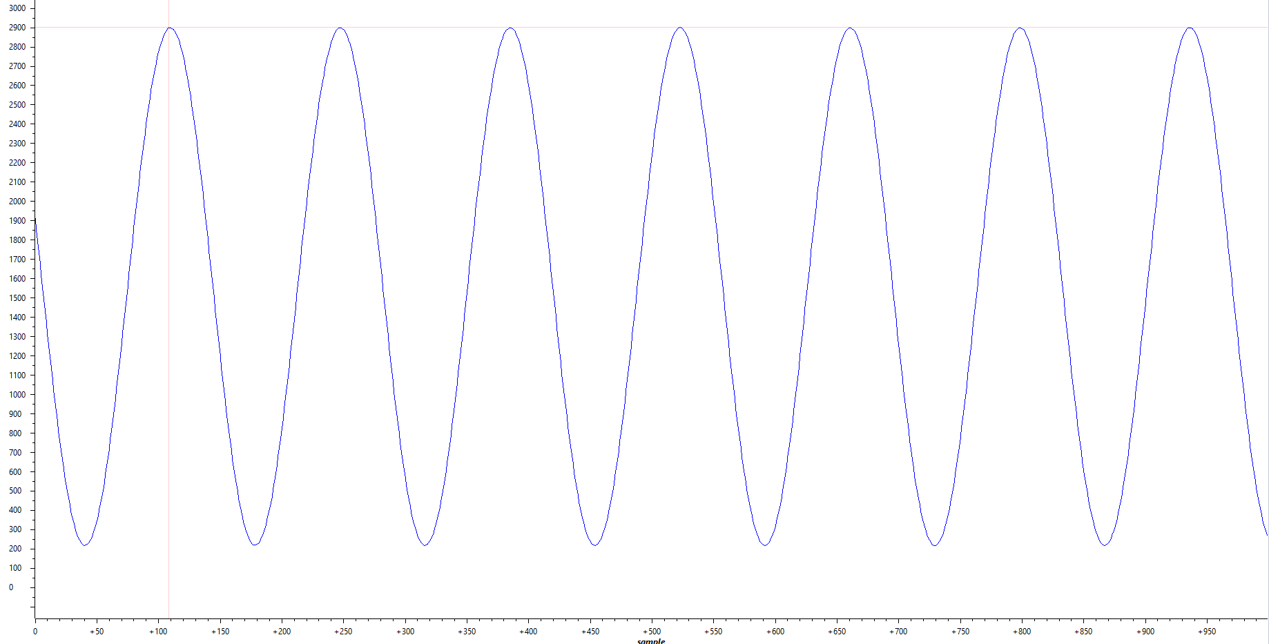
Between each peak there is 140 points. Assuming that we write the tab only when h>200 we have in reality 140*200 = 28'000 points between two peaks for a 3 Hz sine, which means it's 28'000*3 = 84'000 points per second, which gives 84 kHz signal and not 100 Hz. I really don't know what I did wrong. I mean I really need to sample with 100 Hz and not 84 kHz or more. I don't know how it's possible since I think I have well configured the ADC. Please any help would be appreciated.
Thank you very much,
Regards,
Mike
**Attention** This is a public forum


