This thread has been locked.

If you have a related question, please click the "Ask a related question" button in the top right corner. The newly created question will be automatically linked to this question.

MSP430FR2311: Interfacing UART to I2C

Part Number: MSP430FR2311
Other Parts Discussed in Thread: MSP-FET, UNIFLASH

Dear TI Technical Support Team,

We're developing wireless communication devices, and it requires UART-to-I2C bridges to control GPIOs in the system.
and we're trying to interface UART to I2C using MSP430FR2311.
Our goal is to send commands to an I2C chip under the configuration below.
CPU --> USB Hub --> USB to UART converter --> UART to I2C bridge(MSP430FR2311) --> I2C Expander

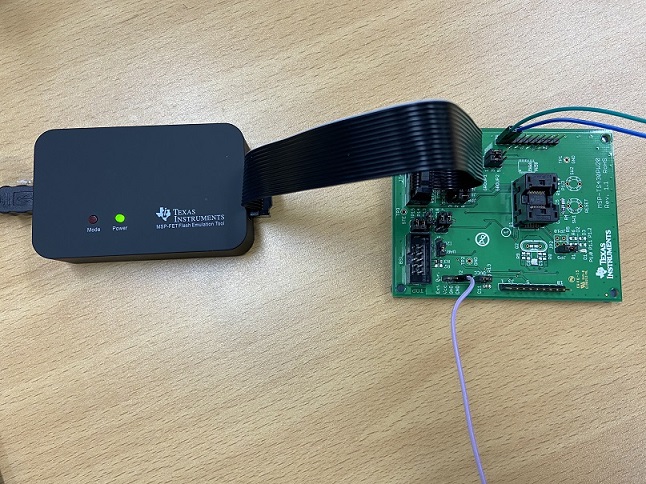
For the verification of the chip, we've purchased standalone MSP430FR2311PW20 chips and MSP-FET debugger.

The application note SLAA908 describes a program that converts between UART and I2C protocols.
However I need some more details because I don't have any backgrounds regarding this.
so I'd like to ask some questions here.

1.
In introduction, it says I should download the project files and a code example in the link below.
www.ti.com/.../slaa908

I installed CCS, then created a project using downloaded files, and built 'debug' for the new project, and debugged the project.
As far as I understand, now the chip contains the UART-to-I2C bridge code inside and it should work as a UART-to-I2C bridge even without CCS.
Is it correct?

2.
If yes, we can send I2C commands through the UART interfaces and it converts into I2C signals, is it correct?
If not, do we have to write a new code for our UART-to-I2C application?

3.
In page 3 of SLAA908, it says that

"Using a PC, open a new serial connection with a terminal program, and connect to the back-channel
UART interface on the MSP-FET by selecting the COM port called MSP Application UART1. In the
terminal window, change the baud rate to 115200. To demonstrate the functionality of the UART-to-I2C
bridge, enter a string of bytes into the terminal window follow command formats and send it. It will be sent
to the I2C slave device, and whatever value was in the TX buffer of the I2C slave device will be displayed
in the serial terminal."

I was following this, but I am not clear of how should the MSP-FET be configured for doing this.
The MSP430FR2311 chip is mounted on, and MSP-FET is connected to the USB port of PC,
and the jumpers of MSP-FET is set as described in the application note.
After that I opened a TeraTerm terminal and chose a serial connection option(MSP Application UART1), set the baud rate to 115200.
Is that all I need to do? or do I have to be opening the CCS and go to a debug mode?

4.
If I follow what is instructed in page 3 of SLAA908,
and then pull-up J4.19 and J4.20 (I2C_SCL and I2C_SDA, respectively)
I could be able to see the waveforms at I2C_SDA pin(J4.20 in MSP-FET) using an oscilloscope,
when I send I2C commands to the UART interface. Is it correct?

The questions may be rambling because I'm quite new to this area.
Any comments or advice would be greately appreciated.

  • Hi Gyuwon,

    For Q1:

    You just need to down the demo into MCU via UniFlash or CCS/IAR, and then, according to the protocol described in the document, the UART TO I2C bridge function can be realized without the need to connect to CCS all the time. CCS is just a debugging and downloading software.

    For Q2:

    We provide the exampke code that can realized the function(UART to I2C Bridget), you just need to down into MCU.

    For Q3:

    After downloader the demo into MCU, we just use the MSP-FET to connect and test the function, because the MSP-FET have a UART port, you can refer to this document to learn the usage of MSP-FET:

    https://www.ti.com/lit/ug/slau647o/slau647o.pdf

    For Q4:

    In order tocheck if the data is correct, you can analyze it according to the results of the oscilloscope waveform or communication data.

    PS: I am the author of this Applicaiton Note(Slaa908), if you have any questions, you can contact me directly。

    Best Regards

    Johnson

  • Thank you for your comments.

    I have done debugging and downloading the provided IAR code for UART-to-I2C to the chip.

    As far as I understand, now I can use the UART-to-I2C interfacing function with MSP-FET connected to the PC.

    The MSP-FET is connected with the TS430PW20 target development board with MSP430FR2311 mounted on it.

    The configuration is as follows:

    PC <------USB cable------> MSP-FET <------JTAG cable------> TS430PW20(MSP430FR2311).

    But when I measured the voltage of J4.20(I2C SDA pin), it's voltage is between 0.3-0.4V.

    I thought these(SDA and SCL, J4.20 and J4.19) should be pulled up with a 4.7k pullup resistor, so I configured so.

    Then I opened a Tera-Term terminal on PC, opened a serial connection through MSP Application UART3 port,

    and sent keyboard inputs through the Tera-Term terminal.

    Then MSP430FR2311 should be receiving some ASCII code inputs in binary through UART lines, 

    I tried to check the logic level waveforms at I2C SDA pin using an oscilloscope, but I couldn't find anything.

    There was just a flat 3.3V...

  • Hi Gyuwon,

    What is the slave device of I2C? Do you connected?

    In this application, the MSP430 as the I2C master, when this MCU received some date from UART, it will do some standard judgments, if it meets the regulations, then read/write data to the slave via I2C interface, thus you need connect the I2C slave device and send uart data follow the regularation(I had describe this in code and you also can modify those depend on your needs).

    Thanks!

    Best Regards

    Johnson

**Attention** This is a public forum