Other Parts Discussed in Thread: MSP-EXP430FR5739
Hi There! I wanted to implement a simple code that shows an "A" on RealTerm, the code that I used is:
#include "driverlib.h"
uint16_t i;
uint8_t RXData = 0, TXData = 0;
uint8_t check = 0;
void main(void)
{
// stop watchdog
WDT_A_hold(WDT_A_BASE);
// LFXT Setup
//Set PJ.4 and PJ.5 as Primary Module Function Input.
/*
* Select Port J
* Set Pin 4, 5 to input Primary Module Function, LFXT.
*/
GPIO_setAsPeripheralModuleFunctionInputPin(
GPIO_PORT_PJ,
GPIO_PIN4 + GPIO_PIN5,
GPIO_PRIMARY_MODULE_FUNCTION
);
//Set DCO frequency to 1MHz
CS_setDCOFreq(CS_DCORSEL_0,CS_DCOFSEL_0);
//Set ACLK = VLO with frequency divider of 1
CS_initClockSignal(CS_ACLK,CS_VLOCLK_SELECT,CS_CLOCK_DIVIDER_1);
//Set SMCLK = DCO with frequency divider of 1
CS_initClockSignal(CS_SMCLK,CS_DCOCLK_SELECT,CS_CLOCK_DIVIDER_1);
//Set MCLK = DCO with frequency divider of 1
CS_initClockSignal(CS_MCLK,CS_DCOCLK_SELECT,CS_CLOCK_DIVIDER_1);
// Configure UART pins
//Set P2.0 and P2.1 as Secondary Module Function Input.
/*
* Select Port 2d
* Set Pin 0, 1 to input Secondary Module Function, (UCA0TXD/UCA0SIMO, UCA0RXD/UCA0SOMI).
*/
GPIO_setAsPeripheralModuleFunctionInputPin(
GPIO_PORT_P2,
GPIO_PIN0 + GPIO_PIN1,
GPIO_SECONDARY_MODULE_FUNCTION
);
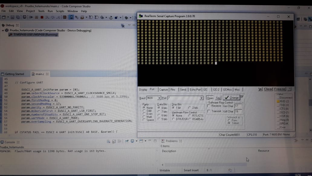
// Configure UART
EUSCI_A_UART_initParam param = {0};
param.selectClockSource = EUSCI_A_UART_CLOCKSOURCE_ACLK;
param.clockPrescalar = 3;
param.firstModReg = 0;
param.secondModReg = 92;
param.parity = EUSCI_A_UART_NO_PARITY;
param.msborLsbFirst = EUSCI_A_UART_LSB_FIRST;
param.numberofStopBits = EUSCI_A_UART_ONE_STOP_BIT;
param.uartMode = EUSCI_A_UART_MODE;
param.overSampling = EUSCI_A_UART_LOW_FREQUENCY_BAUDRATE_GENERATION;
if (STATUS_FAIL == EUSCI_A_UART_init(EUSCI_A0_BASE, ¶m)) {
return;
}
EUSCI_A_UART_enable(EUSCI_A0_BASE);
EUSCI_A_UART_clearInterrupt(EUSCI_A0_BASE,
EUSCI_A_UART_RECEIVE_INTERRUPT);
// Enable USCI_A0 RX interrupt
EUSCI_A_UART_enableInterrupt(EUSCI_A0_BASE,
EUSCI_A_UART_RECEIVE_INTERRUPT); // Enable interrupt
__enable_interrupt();
while (1)
{
TXData = 65; // TX data="A"
// Load data onto buffer
EUSCI_A_UART_transmitData(EUSCI_A0_BASE,
TXData);
// while(check != 1);
check = 0;
}
}
//**********
//
//This is the USCI_A0 interrupt vector service routine.
//
//**********
#if defined(TI_COMPILER_VERSION) || defined(IAR_SYSTEMS_ICC)
#pragma vector=USCI_A0_VECTOR
__interrupt
#elif defined(GNUC)
attribute((interrupt(USCI_A0_VECTOR)))
#endif
void EUSCI_A0_ISR(void)
{
switch(__even_in_range(UCA0IV,USCI_UART_UCTXCPTIFG))
{
case USCI_NONE: break;
case USCI_UART_UCRXIFG:
RXData = EUSCI_A_UART_receiveData(EUSCI_A0_BASE);
if(!(RXData == TXData)) // Check value
{
while(1);
}
check =1;
break;
case USCI_UART_UCTXIFG: break;
case USCI_UART_UCSTTIFG: break;
case USCI_UART_UCTXCPTIFG: break;
}
}
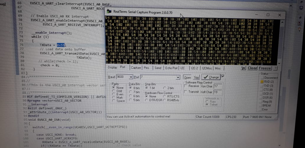
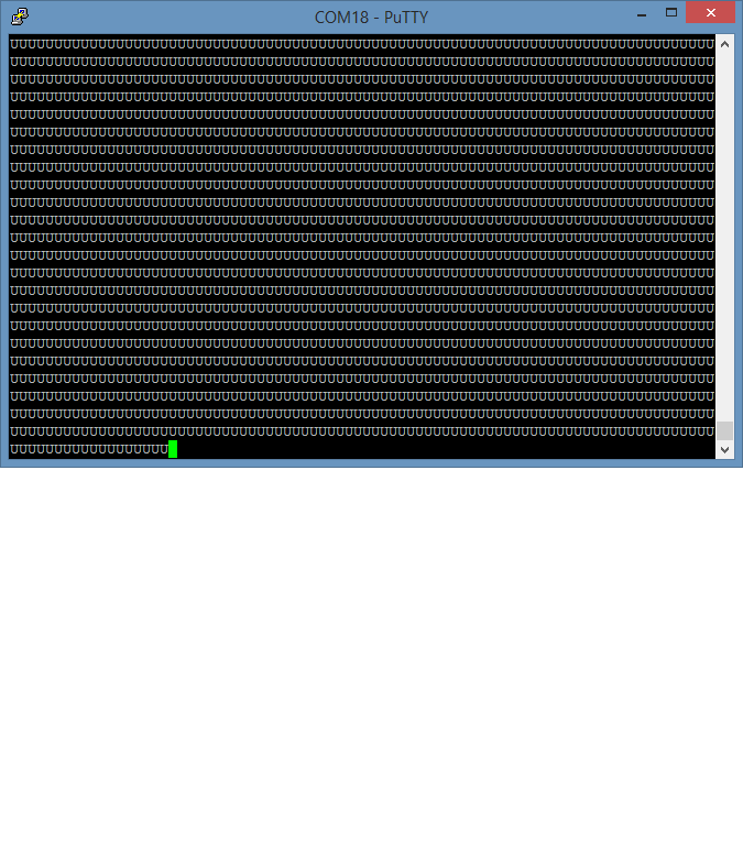
And on RealTerm I see this... (the "<" symbol it is the number 60 is ASCII), if you can see, i assigned TXDATA=65.
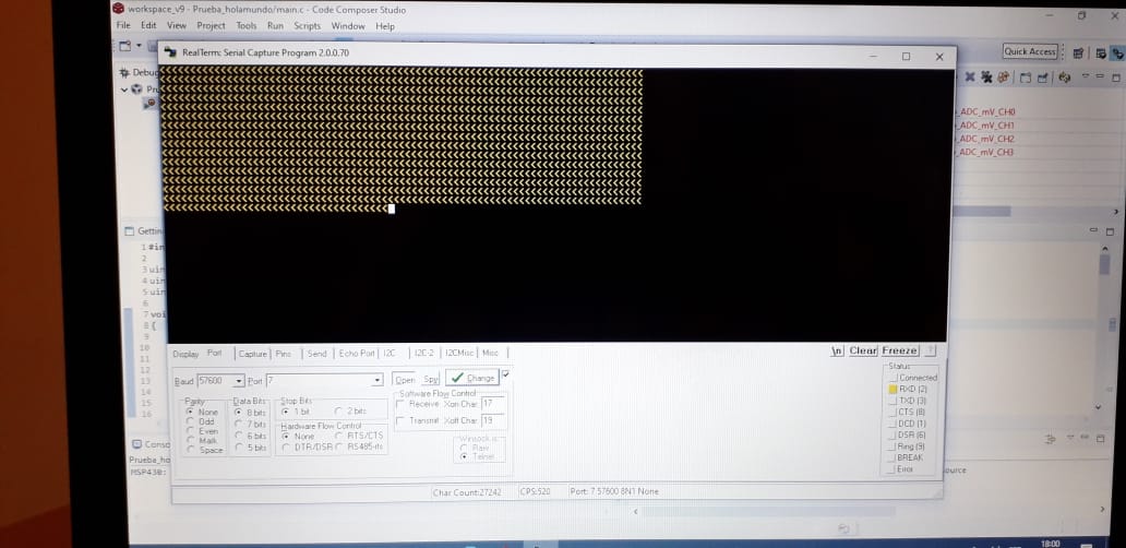
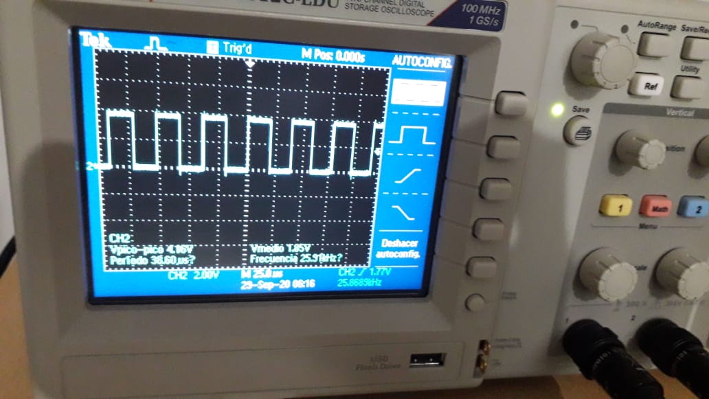
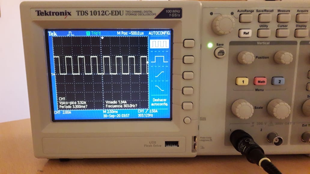
I think it's an error on the CLOCK configuration, bit I can't figuring out... what do you think?
As alwayss.. Thanks!