A related question is a question created from another question. When the related question is created, it will be automatically linked to the original question.
If you have a related question, please click the "Ask a related question" button in the top right corner. The newly created question will be automatically linked to this question.
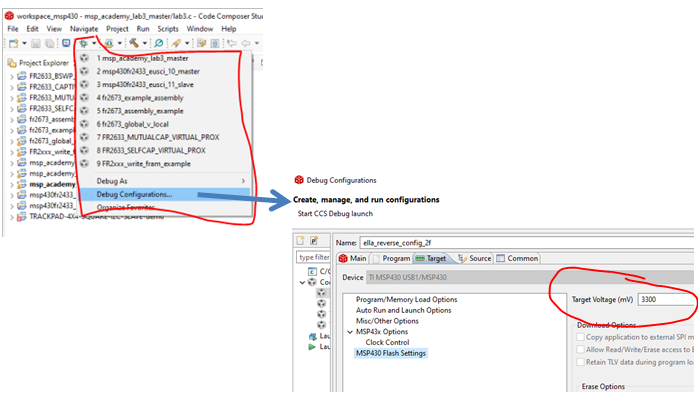
Open debug configurations by clicking small arrow next to green BUG symbol. Find your debug configuration (same as project name) then click on Target TAB. Select MSP430 FLASH settings and set the voltage.
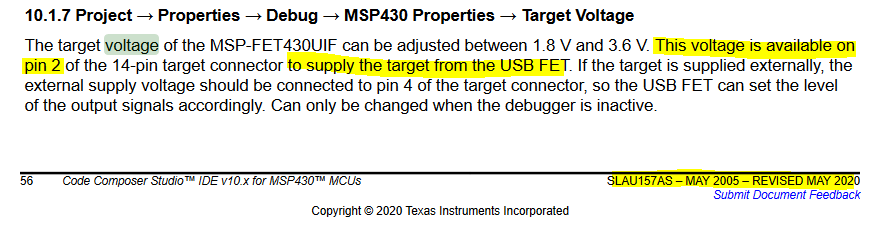
The setup above is for VCC_target. (which is an input for the signals logic levels).
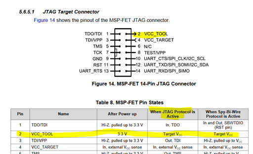
I'm looking for VCC_TOOL which is an output.
By the way, the VCC-Target setting is not really working, I had to actually connect the VCC from my target to this pin in order to run the MSP-FET properly.
I did that. the voltage on PIN2 is 0.2-0.3V. the MSP-FET is new from the BOX.
I'm using my onboard power supply and now it is working.
The problem is that I have to retain some constants and parameters on the FLASH on section that are not in use by the code or variables.
In order to do so, I thought that using the option of "By address range" in the DEBUG->MSP430 options menu. but when I choose this option, there is no place to specify the address range.
Ok. I dug up my MSP430 FET and connected my MSP430 to PIN 2 as shown below and it works for me. NOTE: The VCC voltage won't appear until you start a programming sequence!!!
If you tried the same as me and still not working, what version CCS are you using?
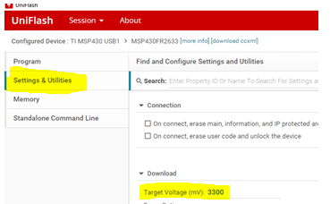
Another thing you can try is Uniflash. There is a cloud version or you can install desktop version. In either case there is a configuration window where you set the voltage. You will need to first compile your code and generate an output file, .out or .txt. The Uniflash interface is simple to use.
Tried all the above option and still Pin #2 is not functional.
I can live with that. but the other problem that i mentioned is much more crucial.
The problem is that I have to retain some constants and parameters on the FLASH on section that are not in use by the code or variables.
In order to do so, I thought that using the option of "By address range" in the DEBUG->MSP430 options menu. but when I choose this option, there is no place to specify the address range.
I used to work with the XDS110 (actually i used the LAUNCHPAD of the MSP432 and disconnect the TMS and TCK from the LAUNCHPED msp432 target and connect it to my msp432). and i didn't have that much troubles. perhaps the MSP-FET is not such a good choice?
Ok, moving on, if you are trying to store some values, such as calibration numbers or some variable so its value is retained through a power cycle, you can write these to the MSP430's 'info' memory. Which MSP are you using?
I'm also confused regarding the MSP-FET, i thought it would be easier to work with but it is slower and less convenient than the workaround with the LAUNCHPAD.
regarding the second issue :
I'm using MSP432P401R, and I have allocated some parameters and calibration tables at addresses 0x3C000 - 0x3FFFF.
these addresses are erased if I use the regular options (program main memory etc..).