This thread has been locked.

If you have a related question, please click the "Ask a related question" button in the top right corner. The newly created question will be automatically linked to this question.

MSP430F249: TI MSP + FET flash Emulator

Part Number: MSP430F249
Other Parts Discussed in Thread: UNIFLASH, , MSP430F2619S-HT

HI

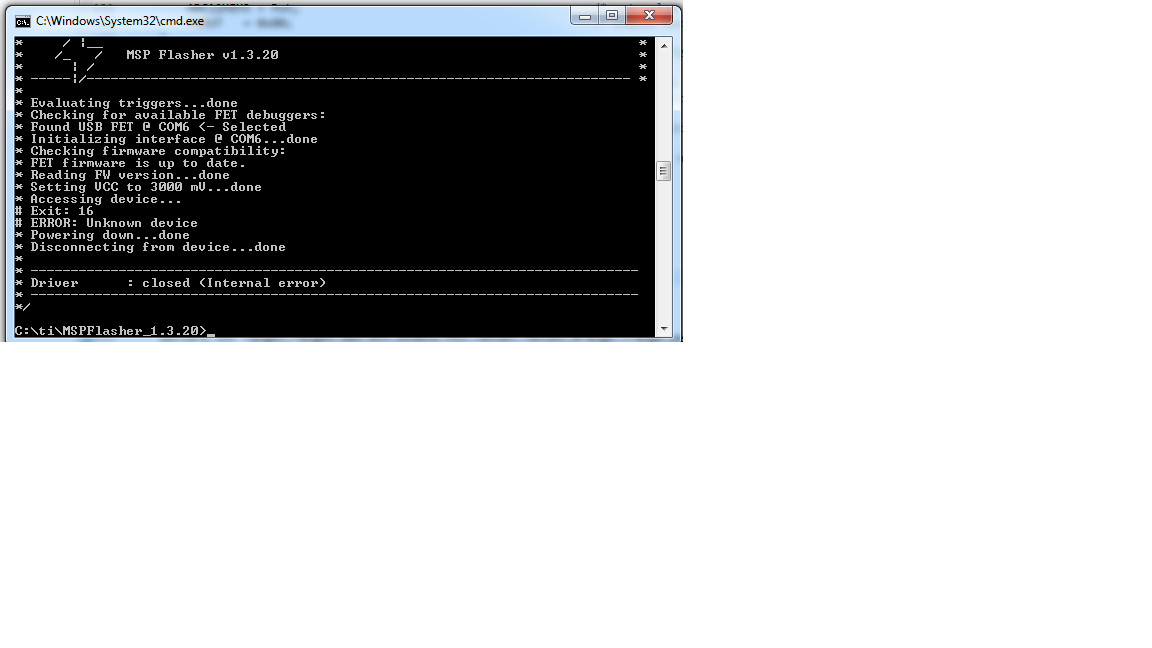
i have a customised board and i used to program it using TI MSP + FET flash Emulator but today it suddenly shows an error that  "MSP430: Error connecting to the target: Unknown device"  trying the check using MSP flasher did nothing

  • Hello sasi,

    Have you been able to program the target successfully in the past or is the first time?

    Are you using 4-wire JTAG or 2-wire "SPY-BY-WIRE" programming connections?

    Do you have a 47K pull up resistor and 1.0nF capacitor to ground on /RST pin?

  • hello Dennis,

    I am using this for past eight months it was working fine, i am using Jtag configuration, and a pull up resistor and capacitor to ground is provided, while debugging was running USB connecting the MSP+Fet to cpu got removed. from that point i am unable to proceed Most likely my MSP Fet is unable to the microcontroller, I tried uniflash and it cannot detect the device, but i don't see any hardware fault such as

    VCC - 3.3v;

    TDO - 3.3V (When connected to FET debugger); 8.7mv when not connected

    TDI - 3.3v

    TMS - 3.3v

    TCK - 3.3v

    RST - 3.3v

  • Hello sasi,

    There is a possibility that the JTAG fuse may have accidentally been blown, leaving the MCU permanently protected from communication through the JTAG port.

    Do you have a second PCB that you can test the MSPFET to make sure the issue is not the MCU?

    Else, can you swap out the MCU with a new one?

  • Hello dennis,

    I do have other IC but what is the possibility that it wont get damaged , as it is a fifth ic being replaced without a correct reason , I would like to know if there is a standard procedure so that the fuse will not be blown on certain circumstances

    I cannot use BSL since i have to check the code with debug only method using CCS, IF there is any possibilities if [active - release] mode were used it will blow jtag fuse

    i tried using other MSP430f249 connected it to my lap and it showed "MSP430: File Loader: Verification failed: Values at address 0x1102 do not match Please verify target memory and memory map.

    MSP430: GEL: File: D:\CCS\123\Debug\123.out: a data verification error occurred, file load failed. " and when i connected it to my system it again showed "MSP430: Error connecting to the target: Unknown device" i am unable to connect the other IC

    As a substitute i had MSP430f2619s-HT i used this ic the same thing happens again

  • Ok, I thought you had only the one device that developed this behavior after the debugger is abruptly disconnected during a debug session.  So you are saying you have additional ones caused by removing debugger?

    When the devices worked, was that only with the debugger attached and running debug session or after being programmed they would operate correctly with out the debugger connected?

    Looking into this a bit deeper, the fuse blow pin on the MSP430F249 is the JTAG pin TDI/TCLK pin and requires between 6 to 7v for 1ms, so I'm thinking this not the issue and that something else in your setup may be causing this issue.

    You responded earlier that you had pull up resistor and capacitor tied to /RST pin - can you confirm the pull up resistor = 47K and capacitor = 1.0nF?

    Have you made any modifications to your PCB or changed anything in the setup from when the devices worked until now?

    Are you using our older (grey enclosure) or new (black enclosure) MSPFET?

    How long is the cable that connects the MSPFET to your PCB? (Long cables can cause this issue)

    Where the MSPFET cable connects to your PCB, can you estimate the PCB trace length from the connector to the target. (Long traces from connector to MCU can cause this issue)

    Is the MCU's GND pin connected to a ground pour or large ground path directly back to where VCC is coming from? (I'm looking for possible long ground paths between MCU and single point ground on the PCB)

    Can you share top and bottom PCB layer screen shots of the PCB or a PDF version? (or if you want you can send me a private message and share with confidentiality)

    Are there any other circuits on this board that could potentially generate high voltages or high back emf voltages, such as driving a motor or relay?

  • HI Dennis,

    we are using 1k resistor and 2.2 pf capacitor

    No changes were made in the board

    new (black enclosure) MSPFET is used

    8 inch connector is used, unable to measure the trace length

    pcb layouts are confidential 

    No such circuits that produce high emf

    About the ground path unable to measure that too

  • Hi sasi,

    Just double checking here... your capacitor is 2.2pf or 2.2nF (2200pf)?

    Also, have you made any changes in CCS to your project settings, especially having to do with the MSPFET?

    I'm trying to rule out possible causes for the JTAG fuse getting blown by accident.

  • HI Dennis,

    We changed the capacitor to 2.2 nf and resistor to 47kohm, No special changes has been made in ccs, i think this could be the issue"http://e2e.ti.com/support/microcontrollers/msp430/f/166/t/164648#pi320995=2" but i did try using reset switch i think i cannot pull it out at the right timing, i also tried MSP430 Flasher but still ended up in error:16. I cannot try BSL since the board is customized for 4 wire jtag. is there any possibilities to cure or prevent this 

    Thanks in advance

  • Sasi,

    A few more questions:

    Is your target board powered by the MSPFET during programming or is the board self-powered?

    What is the sequence that you follow to connect the MSPFET to the target board?

    Example - connect MSPFET to USB, then apply power to board, then connect MSPFET to target board, etc...

  • Hello Dennis

    We provide external power to the target board

    As per sequence Target board draws more current when fet is connected to the board and then power is applied so we decided to connect power first and then connect the MSP+Fet debugger

  • Hi Sasi,

    Ok, that should be fine.  I assume when you connect the MSPFET it is already connected to active USB port so it has power.

    Also, can you check what setting you have for security in your project properties as shown here:

  • HI Dennis,

    Kindly find the attached image

  • Hello Sasi,

    Ok, it appears you have everything set correctly.

    Based on everything we have discussed I'm not necessarily convinced this is a JTAG fuse issue.

    Another possible cause is ESD.  When handling your board and the programmer, are you following good ESD guidelines by having the person properly grounded with a wrist strap?  Is the work surface where the board is located properly grounded or are there any possible sources of static electricity nearby?

    Are you doing anything different compared to several months ago when you did not see this issue?  Do yourself perform the programming or someone else handling the PCB?  If someone else, it is same person as done several months ago?  I ask these questions because the big clue is something has changed in your process since a few months ago that is now causing the problem.

    Do you have another MSPFET to try?  Yes I understand you may accidentally lock yet another device if you try, but we need to start eliminating possible causes.

  • HI Dennis,

    There is no possible ESD produced in the circuit yet we are not using any wrist band, obviously even in the past months we did replace the micro controller because of this issue now i want to figure out the issue which causes the problem 

    certainly i have put an order for MSP GANG which will be reaching with in a weak is there any other way, have u gone through the link "http://e2e.ti.com/support/microcontrollers/msp430/f/166/t/164648#pi320995=1"  it says a monoflop has to be provided to the reset signal i do not know how to provide it and for the BSL i have to remove the IC so is there any proper way that these methods could solve my issue

    Thanks 

    Sasikumar

  • Hi Sasi,

    I understand your concern and realize this can be frustrating problem.  I cannot confirm that the solution offered in the other posting will work.  It is not a TI recommended solution so it would be done at your own risk. I have reached out to development tools team in Germany to see if they can help ,so before you attempt that modification, let's wait to hear back from the tools team.

    I may not get an answer until tomorrow though.

  • Hi Dennis,

    We tried to use BSL with a new IC but we cannot connect it since there is no test pin in MSP430F249 , we are waiting for your solution to nullify the Jtag errors

    Thanks and Regards,

    Sasikumar E

  • Hi Sasi,

    This device has dedicated JTAG pins so what this means is the TEST is the TCK pin on this device.

    Refer to section 1.3.1.2 in the MSP430 Flash device bootloader guide.

    Let me know how this works for you.

  • Hi Dennis,

    i tried to reset the jtag using the below configuration but cannot establish it i have some doubts in it

    1. i have provided power MSP+FET do we have to provide external power?

    2.i did connect TDI TDO from MSP+FET do we have to connect them ? and there is no tclk pin in MSP+FET how to proceed with it?

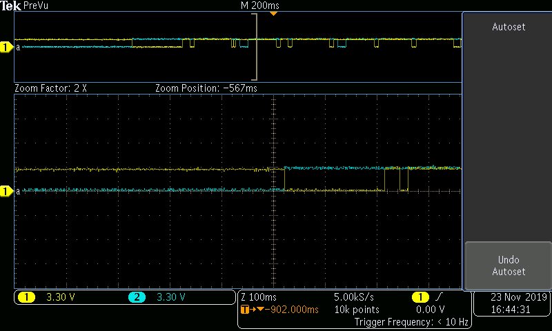
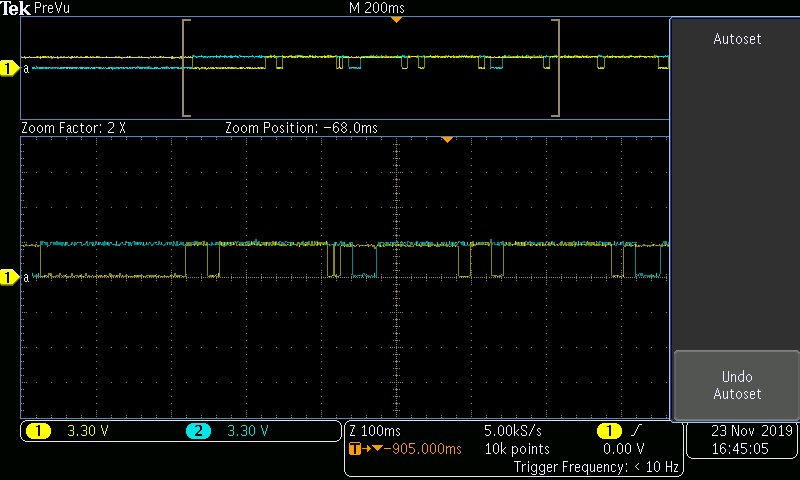
  • I tried to debug and attached debug graph images of TCK-blue line and TMS-yellow line so when power is provided externally both are at logical high state and then when debugger is connected to cpu TMS is logical high and TCK is logical LOW after this external changes provided are not applicable and they stay in a stable state where the provided below configuration does not works 

  • Hi Dennis,

    I think BSL is not working for us, I am going try a new MSP430f249 but I do want to take the precautionary steps before connecting to JTAG

    1.is it ok to program the device only by providing internal power from JTAG 

    2.As you said a high voltage such as (6v/7v) in TDI will break the jtag fuse so what setup has to be made in ccs that it does not breaks the fuse accidentally.

    3. I have read some forum messages that program data could blow the fuse but as per msp430f249 it is physical fuse so it cannot be blown by a program code however this is my initializing code will this provide this error 

    WDTCTL = WDTHOLD + WDTPW;              /* stop watchdog timer */
    BCSCTL1 = 0xA7;                                         /* Basic clock system control 1 - 16MHz */
    DCOCTL = 0x61;                                           /* DCO clock system control */
    BCSCTL2 = 0x04;                                          /* SMCLK in BCSCTL2 divided by 2^2=4 */
    P1DIR = 0xFF;                                               /* P1.0 output-LED ------ Buzz to set max, min, mid value, and LED's to show percentage indication */
    P2DIR = 0xFF;                                                /* Set Port2 as output ---- Seven segment display */
    P3DIR = 0xFF;                                                /* Set Port3 as output ---- Seven segment display */
    P4DIR = 0xFE;                                                /* Set Port4 Bit 0 as input ----- SW to set calib or perc mode */
    P5DIR = 0x00;                                                 /* Set Port5 as input ----- SW to set min, max, mid modes */
    P6DIR = 0x00;                                                 /* ADC input Selected */
    P6SEL = 0x00;                                                 /* disabling port pin buffer to defend parasitic current flow */

    i want to program it through jtag please provide us deatils so that we can proceed further

  • I think BSL is not working for us, I am going try a new MSP430f249 but I do want to take the precautionary steps before connecting to JTAG

    1.is it ok to program the device only by providing internal power from JTAG 

    2.As you said a high voltage such as (6v/7v) in TDI will break the jtag fuse so what setup has to be made in ccs that it does not breaks the fuse accidentally.

    3. I have read some forum messages that program data could blow the fuse but as per msp430f249 it is physical fuse so it cannot be blown by a program code however this is my initializing code will this provide this error 

    WDTCTL = WDTHOLD + WDTPW;              /* stop watchdog timer */
    BCSCTL1 = 0xA7;                                         /* Basic clock system control 1 - 16MHz */
    DCOCTL = 0x61;                                           /* DCO clock system control */
    BCSCTL2 = 0x04;                                          /* SMCLK in BCSCTL2 divided by 2^2=4 */
    P1DIR = 0xFF;                                               /* P1.0 output-LED ------ Buzz to set max, min, mid value, and LED's to show percentage indication */
    P2DIR = 0xFF;                                                /* Set Port2 as output ---- Seven segment display */
    P3DIR = 0xFF;                                                /* Set Port3 as output ---- Seven segment display */
    P4DIR = 0xFE;                                                /* Set Port4 Bit 0 as input ----- SW to set calib or perc mode */
    P5DIR = 0x00;                                                 /* Set Port5 as input ----- SW to set min, max, mid modes */
    P6DIR = 0x00;                                                 /* ADC input Selected */
    P6SEL = 0x00;                                                 /* disabling port pin buffer to defend parasitic current flow */

    i want to program it through jtag please provide us deatils so that we can proceed further

  • Hi sasi,

    In response to your questions:

    1 - Yes

    2 - Working on this

    3 - User code cannot blow the fuse.  What you show is fine.

  • Hi sasi,

    I haven’t heard from you for a couple of days now, so I’m assuming you were able to resolve your issue.
    If this isn’t the case, please click the "This did NOT resolve my issue" button and reply to this thread with more information.
    If this thread locks, please click the "Ask a related question" button and in the new thread describe the current status of your issue and any additional details you may have to assist us in helping to solve your issues.

**Attention** This is a public forum