


Given the broad and highly specialized nature of many motor drive solutions, reviewing schematic and layout is a common question that we expect to see on a weekly basis. Every new project needs a schematic before layout and production. Though the concept is fundamental to most, the mixture of analog, digital, and power careabouts will provide new knowledge unique to motor driver applications.
Note: We recommend reviewing the System Design Considerations for High-Power Motor Driver Applications FAQ and/or application note before designing and reviewing a schematic for higher-power motor applications.
There is fundamental information about what to expect with a motor driver system. Even though there’s information specific to motors, there are lessons that can we can generalize so they can be applied to any device or system in future schematic reviews. The process of conducting a schematic review should match an applications engineer’s own thought process when opening up a schematic for the first time. Figure 1 shows an example of a DRV8353RH schematic that is incorrect and needing to be reviewed, possibly due to the engineer's inexperience in designing a BLDC motor driver system.
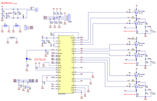
Figure 1 - "Mock" schematic of DRV8353RH (to be reviewed)
After selecting an appropriate motor driver for the system specifications, it is recommended to evaluate the device using an Evaluation Module (EVM) for the device. For instance, the DRV8353RS device has an associated evaluation module called the DRV8353RS-EVM. The purpose of the EVM is to not only provide a system that makes the driver easy to evaluate but also showcase a reliable schematic and layout implementation for such a motor application.
Every EVM comes with additional design files and resources to make schematics easier to create, review, and debug. Look for the “Design files” as a downloadable zip folder on the EVM’s tool page to download the schematic and layout files for the EVM.
The EVM hardware files include output files (.pdf) and design files (Altium). The schematic, assembly, and PCB layer files usually come in PDF format in the top level folder; the PDF schematic is a great tool for quick and easy schematic comparison. For a more comprehensive review, the “Design Files” folder includes the project (.PrjPcb), schematic (.SchDoc), and layout (.PrjPcb), which can all be opened using Altium Designer. Note that a README.txt document describes different EVM variants, such as the SPI and Hardware variants.
Figure 2 shows a breakdown of all of the EVM design files that come in the tool's downloadable zip folder.

Figure 2 - EVM design files in the tool folder including schematic and layout files
When conducting a motor driver schematic review, it is best to understand all blocks of the motor driver system and comprehend how component selection affects each circuit’s functionality. Even though there are recommended components and values in datasheets, take into consideration for the motor driver:
- Capacitor voltage deratings when exposed to DC voltages
- Control interface used and configurability of driver settings
- Pin diagrams of analog inputs, analog outputs, digital inputs, and digital outputs
When designing the power stage using external MOSFETs to switch motor currents and commutate the motor, take into consideration:
- Optional series gate resistors for added gate drive current configurability
- Footprints for gate-to-source resistors or capacitors
- MOSFET selection for application requirements, power losses, and/or parallel configuration
- External components to suppress transients or ringing from parasitics
- Net ties or zero-ohm resistors for easier naming conventions and layout handoff
- Shunt resistor selection for current sense amplifier (CSA) accuracy, power, and low inductance
When designing closed loop feedback in the schematic from the motor’s phase currents, phase voltages, and the bus voltage, take into consideration:
- Filtering required at the CSA outputs
- ADC-scaled phase and bus voltage protection through transient voltage suppression (TVS) diodes and resistor dividers
Lastly, consider the following when designing the motor driver schematic to address system robustness and avoid unwarranted transients or coupling at the motor outputs, supply, or ground:
- Using a common ground versus split ground strategy to minimize inductance, dissipate thermal heat, and reduce noise coupling between motor switching and analog/digital signals
- Addition of bulk capacitance to suppress excessive current demands or dumps from the supply
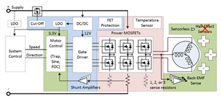
Figure 3 visualizes a high-level look of the BLDC motor driver system and all of the blocks to consider when conducting a BLDC schematic review.
The presentation attached below shows in detail all the blocks in a motor driver system and the considerations to make when creating or reviewing a brushless-DC motor driver schematic. Also attached below is a "mock" schematic using the DRV8353RH filled with many common mistakes seen in BLDC driver system schematics and the reviewed "mock" schematic. The reviewed schematic was conducted by comparing the mock schematic to the DRV8353RH-EVM schematic and implementing the BLDC system knowledge learned from the presentation.
Training (~50 minutes): training.ti.com/how-conduct-bldc-motor-driver-schematic-review-and-basic-debug-tip
Presentation: How_to_do_BLDC_Schematic_Review_and_Debug.pptx
DRV8353RH "mock" schematic: drv8353rs_mock_schematic.pdf
DRV8353RH reviewed "mock" schematic: 0451.drv8353rs_mock_commented.pdf
DRV8353RH-EVM schematic: DRV8353RH-EVM schematic.pdf
We use the EVM schematic to make comments about what we see: what’s good, what bad, and what isn’t there. Luckily, the BLDC schematic review process is systematic and repetitive, so practice makes reviews easier, more comprehensive, and ultimately reduces the time to develop and optimize the system! The goal is to provide a flow that anyone can quickly reference. This ranges from basic component selection to specialized power delivery mitigation techniques, or expected algorithms and features integrated into TI motor drivers. Arming engineers with the tools to get through the first round of debug is key to understanding where to look and what the next steps might be.
