This thread has been locked.

If you have a related question, please click the "Ask a related question" button in the top right corner. The newly created question will be automatically linked to this question.

DRV8303EVM: DC bus current measurement

Part Number: DRV8303EVM
Other Parts Discussed in Thread: CONTROLSUITE, , DRV8329, DRV8323, DRV8303, DRV8328, INSTASPIN-BLDC

Hello,

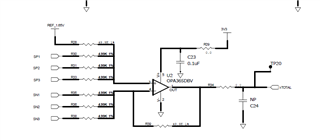
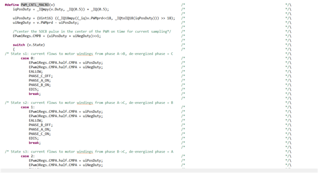
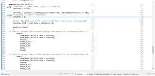
I would like to understand a bit better how the DC bus current measurement works for a BLDC drive. I've bought the TI evaluation module DRV8303EVM and done some testing using the CCS InstaSPIN_BLDC project provided in the controlSUITE (controlSUITE\development_kits\DRV830x-HC-C2-KIT_v105\InstaSPIN_BLDC). I modified the code to be able to just control the PWM duty cycle using the macro PWM_CNTL_MACRO but for a fixed State = 0 which means current flows to motor windings from phase A->B (de-energized phase = C). I then connected the motor winding and run some tests for duty cycles up to 0.15 in order to have some current circulating in the winding. I used a picoscope with a differential probe to measure the signal I-TOTAL from the board which corresponds to the DC bus current signal to the board uC (see board schematic below).

0488.DRV8303EVM_SCH.pdf

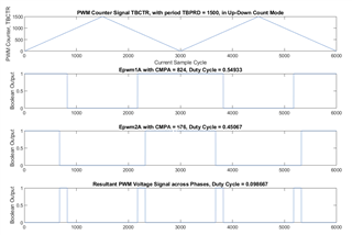
The snapshot below is I-TOTAL for a duty cycle = 0.14. As expected the DC bus current presents pulses and, from my understanding, the actual current value should be the avg of that signal in an interrupt cycle (20kHz in this example). 

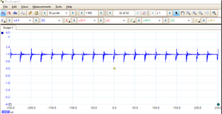
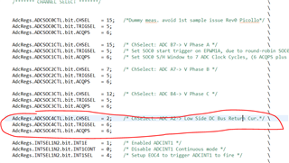
However, looking at how the ADC module is setup in the code to sample the current it looks like the sampling window is very short (ACQPS = 6, hence 7 sample cycles). So, I'm wondering, is this sufficient to capture a large enough portion of the signal for a correct current measurement? 

I'm quite new to the BLDC motor control where only the DC bus current can be measured to implement the six-step control, so I'd really like to understand this better from you. Do you have any documentation/application note I can read?

thanks

Giorgio

  • Hi Giorgio, 

    Thank you for posting your question to the e2e motor drivers forum. 

    I've assigned this thread to a team member, and we will try to provide you with a response next week

    Best Regards, 
    Andrew 

  • Hi Giorgio,

    I appreciate your patience in waiting for a response! The I-TOTAL is the sum of all the total current flowing through the low side shunt resistors. If one or more low side MOSFETs are on, this opens a path for current to flow through the low side shunt resistor and the sum total of all of the currents flowing through the low side shunt resistors would be indicated by I-TOTAL. 

    What I-TOTAL is looking at is how much current is flowing from the motor to ground while the low side MOSFETs are on. So 7 sample cycles should be fine to achieve this. 

    Often, in applications such as trapezoidal control, you will always have at least 1 low side MOSFET on at all times, so you wouldn't see so much of the pulsing that you showed in the waveform, but would instead see the sum total of the motor current flowing out of the motor coils to ground. The inductance of the coils would allow current to continue to flow for some time, even when the high side MOSFET is turned off.

    Regards,

    Anthony Lodi

  • Hi Anthony,

    thank you for the answer and sorry for getting back to you so late. 

    From what I could understand the PWM control method used controls 2 legs at a time (or for a given input State) so that the bottom side MOSFET is not always on (see macro 'PWM_CNTL_MACRO' in header file below). Are you saying that there is a better way of controlling the MOSFETs so that the DC bus current would be less pulsating?

    /cfs-file/__key/communityserver-discussions-components-files/38/f2803xpwm_5F00_cntl_5F00_8301.h 

    Another thing I've noticed, in the header file above there's the following line to sample the current in the center of the PWM:

    /*center the SOCB pulse in the center of the PWM on time for current sampling*/ /* */\
    EPwm1Regs.CMPB = (uiPosDuty + uiNegDuty)>>1; /*

    What happen if the current is sampled at the beginning of the PWM? when also the voltages are sampled? I guess the current measurement would then be wrong because you're sampling outside the current pulse, am I right?

    thanks

    Giorgio

  • Hi Giorgio, 

    Let me aim to get a reply to you middle of next week.

    Regards,

    Anthony Lodi

  • Hi Giorgio,

     You are correct that the PWM control method controls 2 legs at a time, so there will always be one of the low side MOSFETs of at least 1 phase on at all times. With an inductive load (motor) attached with sufficient current, the current will continue to flow through the low side MOSFET back to the supply while spinning the motor. the ITOTAL looks at the sum of all the currents flowing through the low side FETs. I don't see an issue with the ADCs looking at this current specifically when the MOSFET is switched on. 

    Regarding your question on what would happen if the current was sampled at the beginning of the PWM, the answer is that if you sample right on the edge of the PWM then you would not have given sufficient time to allow for the MOSFET switching to take place, which could result in inaccuracies during the current sampling that could occur due to voltage ringing during switching or due to the effects of not having a MOSFET fully turned on when sampling. The current is calculated based on the voltage drop across the shunt resistor, so if there is MOSFET switching occurring then the voltage will not be as accurate..

    Have you considered evaluating some of our newer devices such as DRV8329 or DRV8323? The DRV8303 is an older device and you may find that the newer devices will better suit your needs. Some of the control algorithms on our newer EVMs are slightly different then the control algorithm on the DRV8303. 

    Regards,

    Anthony Lodi

  • Hi Anthony,

    I've actually designed and I'm now testing an inverter where I used the DRV8328 as gate driver. The application is still BLDC motor control and I'm still sampling only the DC bus current.

    Regarding the PWM control, the PWM module is configured to use Up-Down Count Mode for the PWM Counter. I've created an example where I set a duty cycle of 0.1. Therefore, having the PWM period PWMprd = 1500, we'll get: 

    iqPosDuty = _IQmpy(v.Duty, _IQ(0.5)) + _IQ(0.5) = 0.55

    uiPosDuty = (Uint16) ((_IQ18mpy((_iq)v.PWMprd<<18, _IQtoIQ18(iqPosDuty))) >> 18) = 824

    uiNegDuty = v.PWMprd - uiPosDuty = 676

    From my understanding, during the time both Epwm1A and Epwm2A are high both legs will have their high side MOSFETs ON and their low side one OFF. Is that correct or am I missing something here?

    thanks

    Giorgio 

  • Hi Giorgio,

    Let me look into this in more detail and get back to you early next week. If this is what is happening this is a less traditional way of controlling the motor current during motor acceleration/operation (though it would still be a viable option I believe). If 2 legs have their high side MOSFETs ON at the same time and the other leg in Hi-Z (both high side and low side MOSFETs off), then the current would be recirculating through the high side MOSFETs.  

    Regards,

    Anthony Lodi

  • Exactly! And that's the reason why I measure this pulsing current... 

    If there's a better way of controlling the PWM for a BLDC motor, could you please point me to some resources in ControlSUITE where this is implemented?

    thanks

    Giorgio

  • Hi Giorgio,

    I would recommend diving into the sensored trapezoidal Firmware for the DRV8329EVM. That code uses 1 low side CSA to monitor the sum of the phase currents, and the control uses the more common Trapezoidal control method of one leg in Hi-Z mode, one leg with the low side MOSFET on, and one leg synchronously PWMming the high side and low side MOSFET at the desired duty cycle. The DRV8329EVM sensored trapezoidal firmware can be found on the DRV8329EVM product page under the "Order & Start Development" section of the page. 

    Regards,

    Anthony Lodi

  • Hi Anthony,

    thank you for this. The problem I have now is that the firmware for DRV8329EVM was developed for the f28004x microcontroller family and I'm using the f2803x family in my project. Could you please help me modifying the code on my side to implement the same PWM control (I've copied the .h file below)?

    /cfs-file/__key/communityserver-discussions-components-files/38/pwm_5F00_cntl_5F00_8301.h

    I think what I have is not too far from what you're suggesting, the main thing that needs to change is to PWMming only 1 leg and keep the second leg with the low side MOSFET on. The third leg is already in Hi-Z mode. At the moment I'm PWMming 2 legs instead of only 1 (see screenshot of the code below). 

    Is there a quick way to set 1 leg with the low side MOSFET on? Would that be enough just setting uiNegDuty = 0, or there's a more elegant way? 

    thanks

    Giorgio

  • Hi Giorgio,

    I am going to move this post over to the C2000 team to help you with this since they will be more experienced on the MCU code side of things. 

    Regards,

    Anthony Lodi

  • Please take a look at the application notes, InstaSPIN-BLDC Sensorless Control.pdf at C:\ti\controlSUITE\development_kits\DRV830x-HC-C2-KIT_v105\InstaSPIN_BLDC\~Doc

    You may try to change the ADC configuration codes in f2803xidc_vemf.h file according to the board you used.

  • Hello,

    thank you for that. 

    I've actually started developing my code from what was provided in DRV830x-HC-C2-KIT_v105\InstaSPIN_BLDC, however I would like to modify the PWM macro to get a PWM control more suitable for trapezoidal control which is one leg in Hi-Z mode, one leg with the low side MOSFET on, and one leg synchronously PWMming the high side and low side MOSFET at the desired duty cycle (see what Anthony Lodi was suggesting on the 4th of Nov). What is in DRV830x-HC-C2-KIT_v105\InstaSPIN_BLDC at the minute is different: it's one leg in Hi-Z mode and the other 2 legs PWMming the high side and low side MOSFETs. 

    I've tried to modify the PWM macro (see screenshot below where I commented the lines of the original code) and I've basically set iqPosDuty = Duty (this will control the PWMming leg) and uiNegDuty = 0 (this will set the selected leg with the low side MOSFET on). 

    Could you please let me know if this was the correct way of implementing this or if there was a better/more elegant method? 

    thanks

    Giorgio

  • Yes, you can modify the PWM macro as you did, or you can force the low-side PWM to high directly.