Other Parts Discussed in Thread: , DRV8210P, DRV8212P, DRV8210,
Hi !
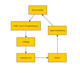
I have been using the DRV8837 H-Bridge since past four years and faced no issues what-so-ever with its performance. It is used to drive a coil with a total inductance < 50 µH and a DC resistance of < 5 ohms, at a frequency of 90 kHz and VM = 3.3V. A small flowchart to describe the function of the whole system is shown below.
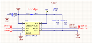
Here is the schematics of the H-Bridge circuitry to drive the coil.
So far, the conditioned signal from the sensor has been without much noise but recently, there were multiple sensors failing at this "noise-test" of the conditioned signals, at a certain temperature range (between 5C and 35C). Since the noise was initially thought of as a sensor problem, the following tests were performed.
- Switch the generator coil between OK sensor and NOK sensor. -> The problem does not follow the coil
- Repopulate the sensing circuitry with OK components.-> no change in result.
- Test the PCB (H-Bridge, µC, sensor) under extreme operating temperatures (Stress test). -> no change in result.
- Adapt the sensing circuitry to filter the noise.-> no change in result.
- Tolerance of the sensor -> found to be within range
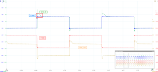
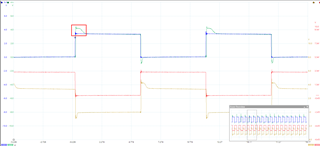
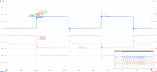
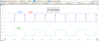
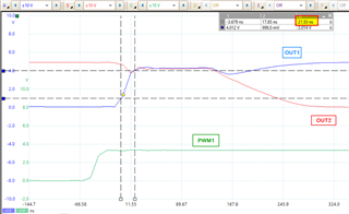
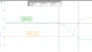
But none of the above resulted in an improvement. During one such tests, the generator coils were probed to see if something is wrong there and the cause of this issue was found to be the energy provided to the generator coil. The oscilloscope was used to measure the actual signal that drives the generator coil, which is shown below.
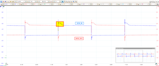
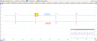
If one notices the highlighted section, there is a clear deviation on how long the charge is help up, before getting discharged from the coil (load). This "charging area" should ideally be <500ns but it is moving up to 650 ns, leading to noisy behaviour from the sensor side. Suspecting that the power provided on the VM side has some noise, RC filters were constructed which unfortunately did not result in much improvement.
Hence, the H-Bridge from an OK sensor was exchanged with an NOK sensor, and the problem followed the H-Bridge. This was done on multiple instance and the results were the same - The issue follows the H-Bridge.
The same H-Bridge has been in usage since last three years on the same sensor (almost 2 years with the same layout) and we have delivered several thousand pieces without issues. It is strange that such an issue pops up at this stage of production, where we have a high demand now to deliver several more.
It will be great if I can receive some help in figuring out why this is happening, and why the issue follows the H-Bridge.
Additional Information
I tried to test with the latest version of H-Bridge (DRV8212P, DRV8210P) and also the other H-Bridge variant (DRV8837C) and on all the three cases, the NOK sensor became an OK sensor. Since the test has not been conducted on multiple sensors, I cannot say for sure if this already makes a case.
Best Regards,
Naveen.