This thread has been locked.

If you have a related question, please click the "Ask a related question" button in the top right corner. The newly created question will be automatically linked to this question.

DRV8316REVM: Motor won't move

Part Number: DRV8316REVM
Other Parts Discussed in Thread: TMS320F28377S, DRV8316

We are using the DRV8316REVM. Here are our observations:

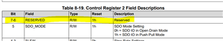
  1. We set control register 2 so that we use PWM_Mode 3x (no current limit). Under these conditions, we cannot move our motor. If we change reserved bit 6 from 1 to 0, then we can move the motor as we desire.
  2. If we set control register 2 so that we use 3x mode with current limit, then we cannot get the motor to move, no matter how reserved bit 6 is set. The current limit on the board is set to 8A, which is far beyond what we need for this motor.

 Can you explain this behavior?

  • Hi Timothy,

    Thank you for posting to the Motor Driver's forum!

    Would you be able to share a waveform of both GHx and GLx in the case where the motor is not spinning?

    Best,

    ~Alicia

  • Hi Alicia,

          I assume that you are referring to the PWM inputs. If not, please let me know which signals I should be looking at.

    Since we are using 3x mode, INLA, INLB, and INLC are all pulled hi.

    When the motor is enabled and ready to run, the INHA, INHB, and INHC are all at ~ 50% duty cycle.

    When we set the registers as indicated in my original email and the motor doesn't move, then INHA and INHB are at roughly 5% and 95% duty cycle - see attached photo.

  • Hi Timothy,

    I assume that you are referring to the PWM inputs. If not, please let me know which signals I should be looking at.

    You are correct, my apologies for the confusion. Would you be able to re-share the waveform image? It appears that it did not go through/is not visible.

    Additionally, would you be able to share a waveform with INHx with OUTx?

    To run this EVM, are you using the InstaSPIN Universal GUI or your own software?

    Best,

    ~Alicia

  • Hi Alicia,

       I put the picture that I described in my previous post for the PWMs that are at 5% and 95% when the motor is not moving. When the motor is in a good state, these PWMs are 50%. FOr the picture with INHA and OUT A, I'm attaching another picture - in this case, the output follows the PWM input until a Fault happens.

    We use our own software, not Instapin. Our processor is the TMS320F28377S. Our software has successfully run BLDC motors using this processor and chips like the DRV8432.

  • Hi Alicia,

            Could you tell me what state we should have for the DRVOFF and the NSLEEP lines when the part is powering up?

  • Hi Alicia,

          I've been working with our firmware engineer Mary West on this problem, and she created a Word document with her observations and questions.DRV8316ControlRegister2Problem.docx

  • When the motor is enabled and ready to run, the INHA, INHB, and INHC are all at ~ 50% duty cycle.

    When we set the registers as indicated in my original email and the motor doesn't move, then INHA and INHB are at roughly 5% and 95% duty cycle -

    Hi,

    since the 3 input INHx are driven by your microprocessor, then why the CPU output are 5% and 95% instead of 50% as the normal motor running case?

    Brian

  • If the motor is failing to move the axis when commanded to do so, the encoder senses it is not moving and provides this input to the DSP. The control loop then tries to send more current - hence the PWMs change accordingly, but no current is actually coming out of the DRV8316.

  • Hi Timothy,

    To briefly answer some of the questions raised in the Word document that you shared.

    • Question:  What are ControlReg_2, bits 6 and 7?  And what are the values and defaults?
      • As shown in the datasheet, these bits are reserved and has a default value of 0x01.

    • Question: What is the time between power-up and SPI communication with the DRV8316? It is not 1 ms.
      • As specified in the datasheet, SPI is ready to be used after power up after tREADY time has passed. 

    For the fault that you mentioned was occurring at start up, which fault was occurring? 

    Best,

    ~Alicia

  • Hi Alicia -

    When ControlReg_2 b7b6 are set to 01b, the IC status is shows up as 0x9 on power-up.  This is a reserved bit (b7) set and the FAULT bit (b0) set to 1.  Status 1 and Status 2 are both 0.  So I don't get any indication what the IC status FAULT is.

    I am aware that the datasheet has ControlReg_2 b7b6 set to 01b.  If I don't set it to 00b, the IC status won't clear and the red LED on the development board won't turn off.

    Again, I am waiting Tready which is 1 ms, but that is not long enough.

  • Hi Mary,

    the IC status is shows up as 0x9 on power-up

    To clarify, when you say IC status, are you referring to IC_Status_Register (Offset = 1h)? If so, if on power-up, this register is being shown as 0x09, then according to Table 8-13. IC_Status_Register Register Field Descriptions, the following bits are set:

    Are you able to share the register values of Status_Register_1 Register (Offset = 1h) and Status_Register_2 Register (Offset = 2h)?

    Best,

    ~Alicia

  • Hi Alicia,

          I see that NPOR is set, but I don't know why. The voltage is 3.1V, which is above the undervoltage lockout specifications. Plus we seem to be unable to clear it, even when Mary sends a 25us pulse on the NSLEEP line.

          I also don't understand this observation: if the DRVOFF line is low, the DRV8316 does not drive the Fault LED; if DRVOFF goes high, the DRV8316 turns on the Fault LED.

    Tim

  • If the motor is failing to move the axis when commanded to do so, the encoder senses it is not moving and provides this input to the DSP. The control loop then tries to send more current - hence the PWMs change accordingly, but no current is actually coming out of the DRV8316.

    Fore ease of debugging, you can keep the pwm = const = 50% and then try to find out why motor not running.

    Brian

  • Hi Timothy,

    When a VM Supply UVLO is detected, the NPOR bit gets reset and latched low until it gets cleared either through the CLR_FLT bit or nSLEEP pin reset pulse. So when the NPOR bit is set to 1, the device is saying that there is not VM Supply UVLO fault.

    Would it be possible to share the values of the other status registers (Status_Register_1 and Status_Register_2) to see if there are any other possible faults occurring that are causing a fault to occur, as indicated by the FAULT bit?

    Best,

    ~Alicia

  • Hi Alicia -

    I shared the Status 1 and Status 2 register values in a previous post.  They were both 0.

    Thanks -

    Mary

  • Hi Mary and Timothy,

    I shared the Status 1 and Status 2 register values in a previous post.  They were both 0.

    Thank you for the clarification, I must have missed it when looking over the post initially. 

    As you are powering up the device, what is the status of DRVOFF and nSLEEP?

    Could you tell me what state we should have for the DRVOFF and the NSLEEP lines when the part is powering up?

    When powering up, DRVOFF, unless you want the MOSFETs to be disabled during power-up, DRVOFF needs to be pulled low and nSLEEP should be pulled high.

    Best,

    ~Alicia

  • Hi Mary and Timothy,

    I am going to close this thread due to inactivity. If you have any further questions, please feel free to re-open this thread or ask a related question.

    Best,

    ~Alicia