Other Parts Discussed in Thread: , TEST2, DRV8231A, DRV8870, DRV8231
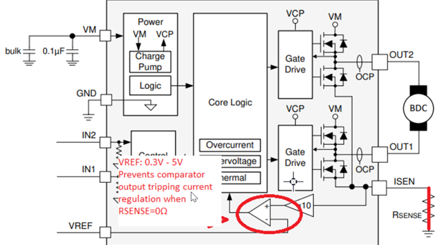
I'm trying to use the VREF pin to set the current regulation level with the DRV8251:
https://www.ti.com/lit/ds/symlink/drv8251.pdf
I'm holding IN1 high, and IN2 Low and using the VREF analog input to set the current regulation level.
Observations:
1) When using a coil that only has 215uH of inductance, the current level was always at full scale and did not respond to the VREF signal.
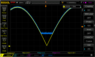
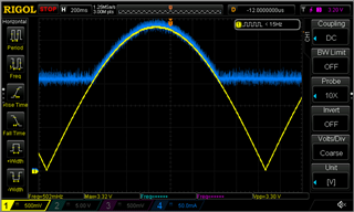
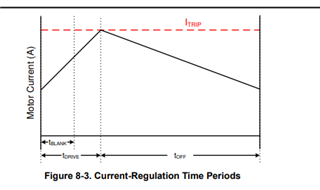
2) When I used another coil with about 3.6mH, the current regulation responded and tracked the VREF pin, but there was a minimum current of about 200mA. It only responded to the VREF signal ABOVE 200mA.
Questions:
1) Is this expected behavior?
2) What is the minimum coil inductance for VREF current regulation? The data sheet does not mention minimum inductance (unless I missed it).
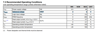
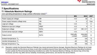
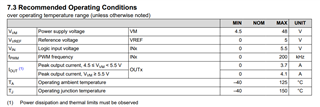
3) Why is there a minimum current of about 200mA when using the VREF current regulation? Is this normal? Again, I don't think the data sheet mentions this. Section 7.3 "Recommended Operation Conditions" lists the VREF voltage range as 0-5V. It makes no mention that the device just ignores all voltages under 200mA.