This thread has been locked.

If you have a related question, please click the "Ask a related question" button in the top right corner. The newly created question will be automatically linked to this question.

MCT8329A: Power up issue

Part Number: MCT8329A
Other Parts Discussed in Thread: MCF8329A, , MCT8316A

Hi,

I have a problem with the motor driver after a power reset. I am using an Arduino to control the driver. I can read and write to all registers and I do get the motor running ok.

However;

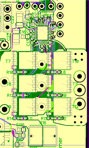
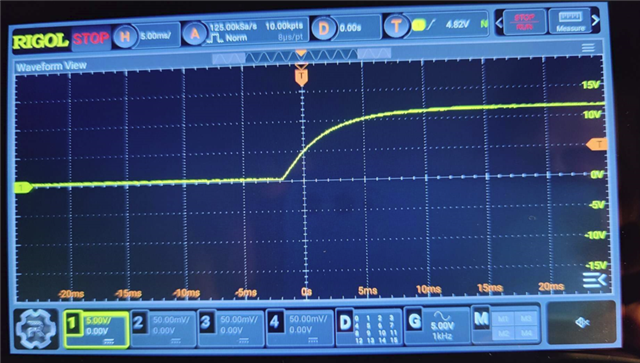
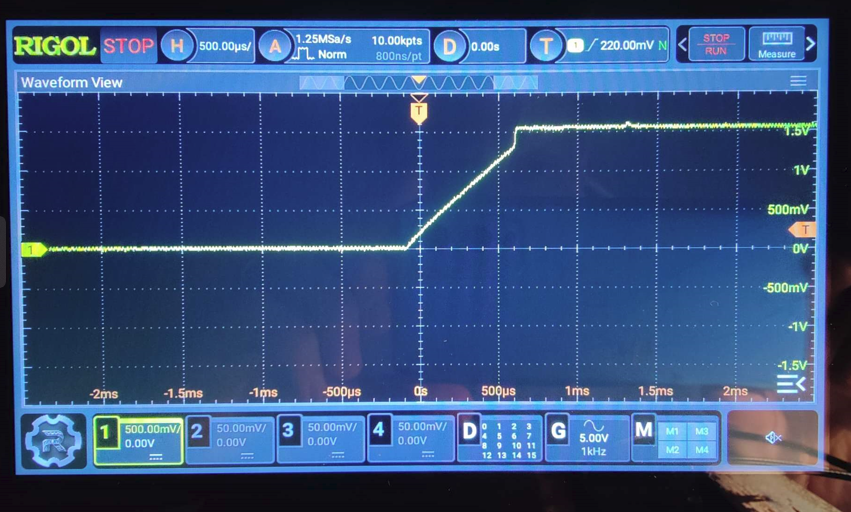
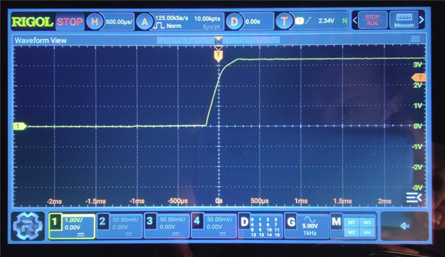
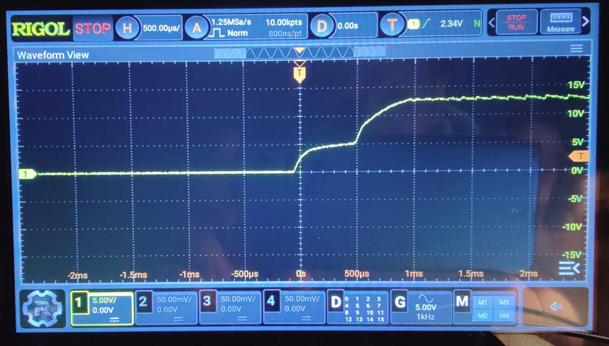
When I keep the logic supply to the arduino and motor driver VREG to 3.3V from the arduino 3.3V regulator using an USB cable from my laptop and do a motor power reset, the system works fine, no issues. But when I disconnect the whole system and let it run of its own power source, which is all powercycled at the same time since the 3.3V is generated from the 12V source, the communication bus on the motor driver crashes. This means I cannot use a communication command to reset the ic. And if I understand there are no available hw reset pins on the driver ic!?! 

Two questions arise;

1. What could be the reason for the motor driver ic to crash completely on a power up, and how can I solve this?

2. I have not connected VREG and AVDD together since I use an external 3.3V supply. COuld this be an issue?

I am super stuck. All help appreciated!

  • Hi Mikael,

    1. What could be the reason for the motor driver ic to crash completely on a power up, and how can I solve this?

    At startup, could you measure the DVDD voltage and make sure that DVDD is outputting a voltage in the range of 1.4V to 1.65V? If DVDD is not in this range then the digital core of the MCF8329A is not powered which is leading to the communication issue. Also, could you measure PVDD and AVDD to make sure PVDD > 4.5V and AVDD > 3.0? If either of these voltages are below their respective values then the digital core will be disabled due to an under voltage fault condition.

    If DVDD is not in the range of 1.4V to 1.65V, please measure the voltage at VREG, make sure that it is still between 3V to 5V, and measure your 12V source to make sure that the voltage has not dropped due to excessive current load.

    2. I have not connected VREG and AVDD together since I use an external 3.3V supply. COuld this be an issue?

    VREG can be supplied by an external supply in the range of 3V to 5.5V (30mA source). So as long as the external 3.3V supply can support the current demand of VREG then there should be no issue.

    Regards,

    Joshua

  • Hi,

    All voltages are within limits and are stable during operation, however, due to large bulk capacitance the power on slope is relatively slow, about 5ms.

    Anyway;

    The issue seems to be related to eeprom settings somehow. At first I just ran the driver with all settings default, and that was when the driver did not start correctly. (However with 3.3V and USB power it ran my motor perfectly good.) When I wrote to all eeprom registers the system starts as expected. Do you have an idea which specific setting this could be about? 

    As a small side question. How can I tune the driver for my motor? Does the eval-kit and gui have any built in function for this kind of work, so that I can bring out the most suitable values for all the registers somehow? I tried to more or less guess all the several hundred bits in the registers which lead to severe unplanned dissassembly.

  • Hi Mikael,

    Are you still having issues with communicating with the MCT8329A or have you resolved this issue and are now having issues with motor startup? 

    For the EEPROM write leading to better startup reliability, is the improved startup reliability consistent across multiple startup attempts?

    For a general guide on tuning the MCT8329A, I would take a look at the MCT8316A Tuning Guide. The general tuning suggestions for the MCT8316A will apply to tuning the MCT8329A as well: https://www.ti.com/lit/ug/sllu336a/sllu336a.pdf?ts=1706039461410&ref_url=https%253A%252F%252Fwww.google.com%252F

    Regards,

    Joshua

  • Hi,

    After populating the eeprom with my own values the startup worked every time, at least 20 attempts. That is why I asked if there are any specific settings related that you could think of.

    Regarding the tuning doc, thanks!

  • Hi Mikael,

    Without more information, like a capture of the phase current when the issue was occurring, I could not make a good guess at what setting could have been causing the startup issues.

    Regards,

    Joshua

  • Yeah, I know. The registers are way to many to be able to grasp. :) Well, there were nothing on the phase currents when this error occured. It does not even try to start. So, If you remember I could start the motor fine if I had 3.3V connected to the logic, before I powered up the motor power. When I remove the logic 3.3V and let it be enabled at the same time as the power(12V). The driver does absolutely nothing and is uncommunicative. So I really don´t think you will get anywhere with the phase current. Could it be an ic ed error? I can reproduce on three different chips. All voltages are stable.

  • Hi Mikael,

    Could you provide me with your schematic?

    Also, can you provide a capture of the PVDD, DVDD, VREG, and GVDD voltages at startup when not supplying 3.3V from the Arduino?

    Regards,

    Joshua

  • Well it is starting fine if I configure the eeprom parameters even without the 3.3V first supplied. If it was about my design, wouldnt that be strange?

    I cant share a schematic since this is part of a bigger system. However I can let you look at my design;

    And here are the sampling of the scope;

    PVDD

    DVDD

    VREG

    GVDD

    I hope it says more to you than to me. Seems ok.

  • Hi Mikael,

    I will need some time to look into this issue. I will get back with you by Friday.

    Regards,

    Joshua