- Ask a related questionWhat is a related question?A related question is a question created from another question. When the related question is created, it will be automatically linked to the original question.
This thread has been locked.
If you have a related question, please click the "Ask a related question" button in the top right corner. The newly created question will be automatically linked to this question.
Tool/software:
Hello Expert,
Could you please tell me maximum input frequency?
We are planning to use 20Hz to 20kHz signal.
But voltage regulation Internal PWM frequency is 44.5kHz
So, I suppose the input signal frequency is limited and it is depends on Voltage regulation setting.
Best regards,
Kazuki Kuramochi
Hi Kuramochi-san,
We are planning to use 20Hz to 20kHz signal.
But voltage regulation Internal PWM frequency is 44.5kHz
So, I suppose the input signal frequency is limited and it is depends on Voltage regulation setting.
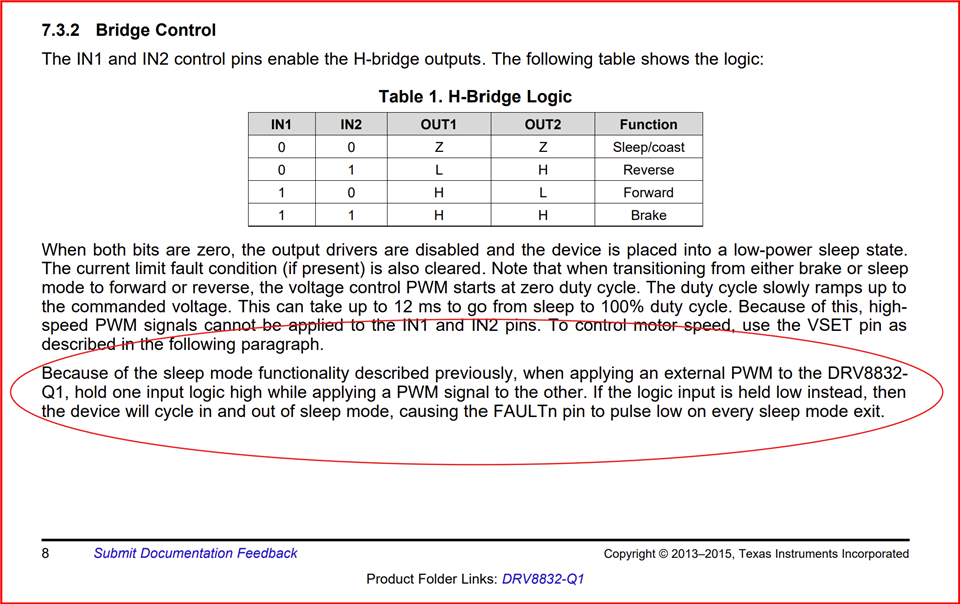
You are correct. Also make note of the below from the datasheet. Thank you.
Regards, Murugavel
Hello Murugavel,
I understand the note for external PWM mode.
Also, could you please provide answer for following question for external PWM input?
Could you please tell me maximum input frequency?
Best regards,
Kazuki Kuramochi
Hi Kuramochi-san,
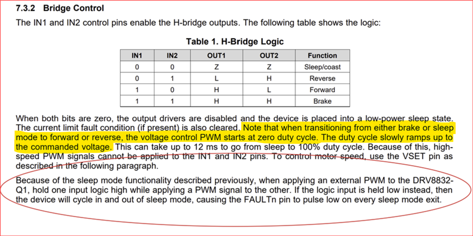
The DRV8832-Q1 is not meant for external PWM control. This is why we do not specify a PWM input frequency. The reason is as mentioned in the below highlighted information. It takes several milliseconds for the motor speed to ramp up from 0 to target speed during every ON time of the external PWM input. So if you have kHz range PWM the time period is in 1ms or less range which is too short for the speed to ramp up to steady state value. If you do want to use PWM control you should consider the target speed, supply voltage which will define the steady state internal duty cycle and ramp up time.
For example assuming you'd be at the top end the device internal duty cycle because of the voltage and speed requirements, it would require close to 12ms to stabilize. Which means ON time of external PWM must be > 12ms which would be ~ 80 Hz with close to 100% duty cycle external input. If you have lower duty cycle requirement then the PWM frequency should be < 80 Hz proportionately.
You could use a faster external PWM in which case motor will never reach target speed during ON time of the external PWM. At some point it will not even spin depending on the supply voltage and motor specifications. So device pin itself does not pose a limitation but external factors and the device functional mode pose this limitation.
What is the application purpose of using external PWM with this device? We have several BDC motor drivers in our portfolio that can do direct PWM control for example with up to 25 kHz PWM input frequency.

Regards, Murugavel
Hello Murugavel-san,
Our customer is considering to use this device for Piezo Driver as Full Bridge driver so there isn't any concern regarding speed stabilization.
I understood this device has slow ramp up function from Sleep or brake to forward or reverse.
I'm asking about the detailed input waveform information but they are considering to use 20Hz~20kHz input signal.
Could you please tell me maximum input frequency of this device under stable condition?
Does you mean this device's maximum input and output frequency is just 80Hz?
Best regards,
Kazuki Kurmaochi
Hello Murugavel-san,
Our customer is considering to use this device for Piezo Driver as Full Bridge driver so there isn't any concern regarding speed stabilization.
I understood this device has slow ramp up function from Sleep or brake to forward or reverse.
I'm asking about the detailed input waveform information but they are considering to use 20Hz~20kHz input signal.
Could you please tell me maximum input frequency of this device under stable condition?
Does you mean this device's maximum input and output frequency is just 80Hz?
Also, this datasheet explanation seems it is for voltage control PWM.
Then, could you answer my question when we disable voltage control function by connecting VSET to VCC?
Please note that we just want to use this device as simple H bridge driver.
Best regards,
Kazuki Kurmaochi
Hi Kuramochi-san,
Thanks for providing the application use case information. With a piezo load the dynamics are definitely different. I was assuming an inductive load that still required voltage control PWM. You are correct, for driving a piezo you have to disable the voltage control function by connecting VSET to VCC. So the device will be a regular H-Bridge. In this case I think a 20Hz to 20kHz input signal can be used with INx. Let me check with the team and confirm with you if this can be supported with no issues. It may take a few days to get the feedback. Thank you.
Regards, Murugavel
Hi Kuramochi-san,
In this case I think a 20Hz to 20kHz input signal can be used with INx.
This may not be the case. We did a quick bench test to see if this works. We ran into an issue. We're checking with the team about feasibility of using the device in this mode. I'll keep you posted. We do not have a concrete answer yet. Thank you.
Regards, Murugavel
Hi Murugavel-san,
I understand current situation and thank you for your confirmation.
I'm looking forward to hearing back from you.
Best regards,
Kazuki Kuramochi
Hi Kuramochi-san,
Even if the VSET is connected to VCC to disable regulation the output ramps to 100% duty cycle from zero when INx is enabled. This cannot be bypassed. See below scope shot taken with VSET = VCC. Yellow is OUT1 and pink is IN2. IN1 = 0. Notice the output starts high and the internal PWM ramps up in duty cycle (active low) until it reaches OUT1 = 0, during this time OUT2 = 1. I changed the voltage scale for the two traces for better visibility. Every time the output transitions from brake or sleep to full on it would take ~12ms to ramp up with the internal PWM 0 to 100%. This is why this device cannot support high frequency PWM input hence no spec in the datasheet. This device is not intended to be used with external high speed PWM input.
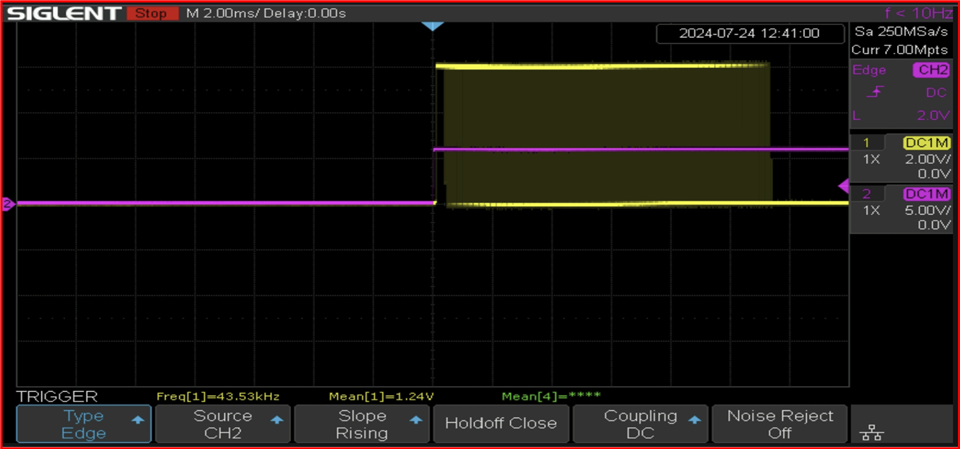
Because of this reason the output will be active only after 12ms every external PWM on time. This means the PWM on time must be > 12ms to make sense. This device is not suitable for the piezo application with high frequency PWM external inputs.
Customer should consider H-bridge drivers such as the DRV8210, DRV8210P, DRV8212, DRV8212P for driving a piezo. Thank you.
Regards, Murugavel
Hi Murugavel-san,
It is bad news for us but I understand.
As we asked about DRV8832-"Q1" so this is for automotive application.
Your propose device don't have Q1 version so we cannot use those device.
Could you please tell me your recommendation from Q1 qualified device?
Best regards,
Kazuki Kuramochi
Hi Kuramochi-san,
Yes unfortunately so. It is not suitable for driving a piezo which requires PWM in the audible range and may be a variable frequency. This device is intended for a standalone voltage controlled integrated speed regulation for BDC applications.
What is the operating voltage, is it 12V? Please take a look at DRV8801A-Q1, DRV8876-Q1. These devices can support up to 100kHz. Note, the DRV8876-Q1 spread spectrum frequency dithering feature will dither the output, so it may or may not impact the piezo sound. Customer needs to verify this. Thank you.
Regards, Murugavel
HI Murugavel-san,
Sorry but I'd like to make sure about 12ms ramp time.
You said this behavior happen when device state change from Sleep/Brake to Forward/Reverse.
Does it mean we can drive device without 12ms ramp time when we change state from Forward to Reverse or Reverse to Forward?
Also, Is this ramp waveform's frequency 44.5kHz?
If answer for first question is yes, could you please provide following information?
For 2., IN1/2 will change status simultaneously under ideal condition but actual circuit will have some delay and mismatch between IN1/2.
So this mismatch will cause very short term Sleep and Brake command from IN1/2.
I guess that such a short term input condition will be ignored but there isn't this information on datasheet.
So I'd like to confirm this.
Also their VIN is 5V so the candidate is only DRV8876-Q1 from your suggestion.
Could you please disclose more detail about spread spectrum function?
Datasheet only have description as below at top page.
"Spread spectrum clocking for low electromagnetic interference (EMI)"
As far as my understanding, DRV8876-Q1 reflect input pin condition as long as current regulation happen.
So I think switching behavior only happen during current regulation and Spread Spectrum only happen in this mode.
Therefore, we can eliminate negative impact from spread spectrum if I set current regulation threshold as very high.
Best regards,
Kazuki Kuramochi
Hi Kuramochi-san,
Also, Is this ramp waveform's frequency 44.5kHz?
Yes this is correct. It is 44.5kHz PWM ramping from 0% duty cycle.
How does the customer intend to drive the inputs without encountering the below highlighted logic combination? Let's say they're driving in Forward. So for example, IN1 = 1 and IN2 = PWM 2 KHz, with some duty-cycle. How can the Brake state be avoided? Every time the device exits from the Brake state the internal PWM ramps from 0% duty cycle. That's how the internal logic works. So exiting from 0,0 input or 1,1 input combination to either 1,0 or 0,1 input combination will start the internal PWM ramp up. Did the customer evaluate the device with these combinations with an EVM?

Could you please disclose more detail about spread spectrum function?
The spread spectrum modulates the internal digital clock frequency by +/- 10%. This helps spreading the peak fundamental EMI energy to a wider frequency spectrum with significantly lower peak. Likewise the charge pump switching frequency is also dithered.
As far as my understanding, DRV8876-Q1 reflect input pin condition as long as current regulation happen.
So I think switching behavior only happen during current regulation and Spread Spectrum only happen in this mode.
Therefore, we can eliminate negative impact from spread spectrum if I set current regulation threshold as very high.
Not really. The dithering will be present regardless of current regulation enabled or disabled. The output edges will be dithered because the internal digital state machine timing will be modulated dithering dead-time, propagation delay and switching timings. The output edges (rising and falling) would be dithered by a few hundred ns. This is how switching EMI will be reduced by spread spectrum. This technique is widely used in power switching ICs such as motor drives, high current switching power supplies etc. The dithering range of the output edges is not influenced by input PWM frequency, it is a fixed value.
That said, I think this dithering may likely not be perceivable (by humans) as offending audio artifacts. I brought this up such that customer can be aware of this dithering and evaluate this device with their piezo to ensure suitability of using this device for their application.
Regards, Murugavel
Hi Murugavel-san,
For your question "How does the customer intend to drive the inputs without encountering the below highlighted logic combination? ", I want to know about whether there is 12ms when they toggling forward and reverse.
They datasheet said 12ms will happen when we change status from brake/sleep to forward/reverse.
In ideal condition, this event won't happen when we toggle reverse and forward.
However, as I asked, short term brake/sleep will happen when we toggle forward/sleep in actual condition.
So I'm asking you about "Will 12ms ramp happen when they toggle mode between forward and reverse directly?"
At this moment, they don't have actual load(speaker) so they cannot test in actual condition.
Therefore we are posting questions from the view point of IC design before testing actual device.
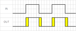
For spread spectrum, my understanding that DRV8876-Q1 adding timing variation at each rising and falling as following yellow area.
Is this right?
Hi Kuramochi-san,
Every time the device exits from the Brake state the internal PWM ramps from 0% duty cycle. That's how the internal logic works. So exiting from 0,0 input or 1,1 input combination to either 1,0 or 0,1 input combination will start the internal PWM ramp up.
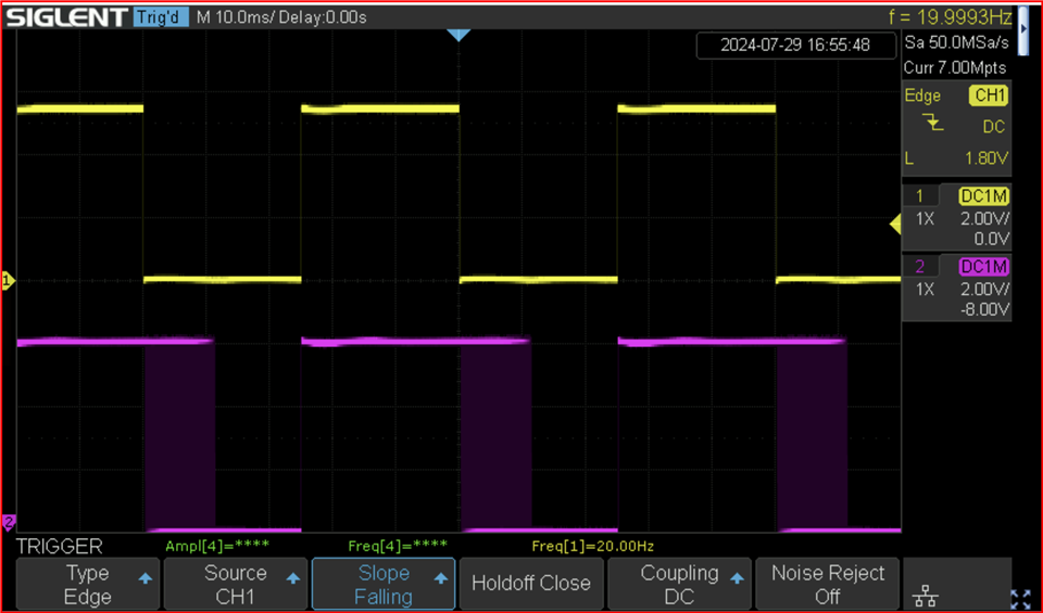
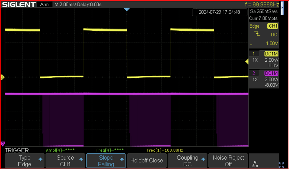
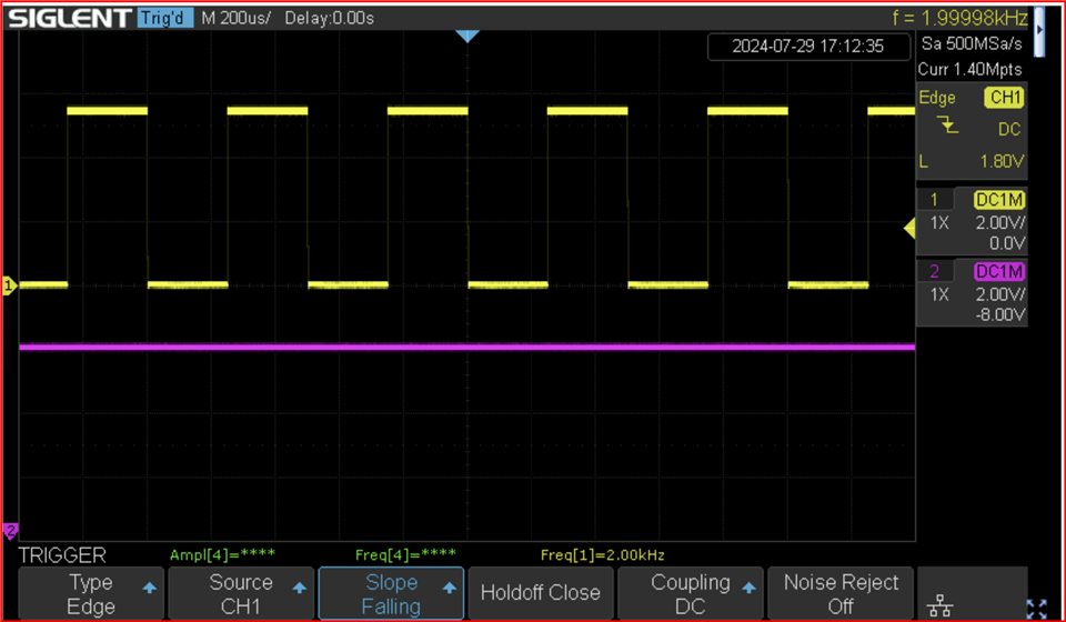
What I was saying was there is no way to avoid a brake happening every PWM cycle operating the bridge in one direction, either forward or reverse. As soon as IN1 = IN2 = 1 the bridge will go to brake mode. Then the next cycle will start, for example with IN1 = 1 and IN2 = 0. If the IN2 = 0 is longer than 12ms the output will be fully ramped up and if it is shorter it will abort mid way and go to brake. See below captures with IN1 = 1, yellow PWM input to IN2, pink is OUT2. VSET = VCC = 6V. Also note there will be a small delay time of ~300us from input active to output active internal PWM start. This means above a certain input frequency there won't be enough on-time for output PWM to start and the outputs will remain at HIGH. Like I mentioned before this device is not designed for external PWM input control.
20Hz PWM input. See the 44.5kHz PWM ramp from 0 to 100% duty for 12ms every PWM cycle. As soon as IN2 = HIGH, OUT2 = HIGH because OUT1 is HIGH already the device will go to brake state and start over at the next PWM cycle when IN2 = LOW, OUT2 = ramp from HIGH to LOW with 44.5kHz PWM 0 to 100% duty cycle.
100Hz PWM input. See the 44.5kHz PWM on time of 5ms way < 12ms so the output never reaches 100% duty cycle.
2kHz PWM. See the 44.5kHz PWM ramp from 0 to 100% duty for 12ms every PWM cycle. PWM on time of 200us is < 300us so there is no output. There won't be any output from about 1.8kHz PWM input and higher frequencies.
For your question "How does the customer intend to drive the inputs without encountering the below highlighted logic combination? ", I want to know about whether there is 12ms when they toggling forward and reverse.
They datasheet said 12ms will happen when we change status from brake/sleep to forward/reverse.
In ideal condition, this event won't happen when we toggle reverse and forward.However, as I asked, short term brake/sleep will happen when we toggle forward/sleep in actual condition.
So I'm asking you about "Will 12ms ramp happen when they toggle mode between forward and reverse directly?"
"In ideal condition, this event won't happen when we toggle reverse and forward". Yes, you are correct assuming both inputs are perfectly synchronized and precisely 50% duty cycle PWM and 180 degrees out of phase there won't be a sleep or brake happening, which means the output may toggle at the toggle frequency without repeating a PWM ramp cycle after it ramped up the first time from 0 to 100% 44.5kHz PWM. The first ramp up cannot be avoided. However please keep in mind, the datasheet does not say toggling reverse and forward continuously at high frequency is a supported operating mode and 12ms ramp up will not happen in between when we do this toggling.
Whether it will work consistently over the lifetime of the device under varying temperature conditions or process variations with a piezo load TI cannot guarantee because this device was not designed and characterized to be used in this mode. I happened to have a means of generating two PWMs with such aforementioned synchronicity and consistency. I tested from 20Hz to 100KHz and it worked as per this theory, yes 100kHz but with no output load. I also tried a very small mismatch/skew between the two inputs and the output was immediately severely affected - the operation was pretty sensitive to timing synchronization of the inputs. So it is up to the customer to determine whether this device will work for them consistently in their application under all required operating conditions in this specific mode. For further questions regarding this device usage in this unintended mode please email me directly.
Regarding the DRV8876-Q1 question:
For spread spectrum, my understanding that DRV8876-Q1 adding timing variation at each rising and falling as following yellow area.
Is this right?
Yes this is correct. See below example output capture from a different H-bridge device, the DRV8262. The input PWM was a negligibly low jitter < 3ns input at 200kHz. All the modulation seen in the output was because of the internal spread spectrum dither.
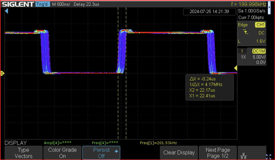
I hope you can close this E2E post now by marking as RESOLVED. I have provided all the answers with corresponding oscilloscope captures. Thank you.
Regards, Murugavel