Overcurrent protection and current regulation are often mistaken for one another. However, there are some key differences that separate these two features apart.
Overcurrent Protection (OCP)
OCP is a protection feature which limits the output current to a safe level in order to prevent any damage to the silicon. This current limit is often called the OCP current threshold (I_OCP) and is a fixed value which is not configurable. If the output current drawn is above the I_OCP value, it can trigger a fault condition which will disable the outputs to prevent damage to the device.
The internal OCP circuit can differ depending if the device has integrated or external H-bridge FETs. For external FET devices, the voltage across the drain-source (VDS) of the FET is measured and compared with the OCP trip voltage level (VDS(OCP)). For internal FET devices, the current through the FETs is measured and compared with the OCP trip current level (I_OCP) In both cases, once the OCP trip level is surpassed for longer than the deglitch time (t_OCP), all FETs in the H-bridge will be disabled and a fault condition will be reported. Certain devices, like the DRV8842, will latch into an off state after experiencing an OCP fault and the FETs can be re-enabled by cycling power or resetting the device. Other devices, like the DRV8847, will re-enable the FETs after some time (t_RETRY). If the OCP fault condition is still present, the cycle will continue until the OCP fault disappears and the device returns to normal operation. There are some devices, such as the DRV8876 and DRV8874, that have latched off and automatic retry OCP modes.
Current Regulation
Current regulation controls the current magnitude across inductive loads. In brushed DC motors, current regulation is used to limit the current during startup or stall conditions. In stepper motors, current regulation is used to define the motion current profile and create the sinusoidal current waveforms.
Current regulation is NOT a protection feature and the current regulation threshold (I_trip) can be adjusted unlike the OCP trip level. The current limit is set and monitored by the current sensing circuitry. The current sensing is integrated in some devices while other devices require an external sense resistor (Rsense) to monitor the output current. http://www.ti.com/lit/an/slvae68/slvae68.pdf is an app note that describes the advantages of integrated sensing.
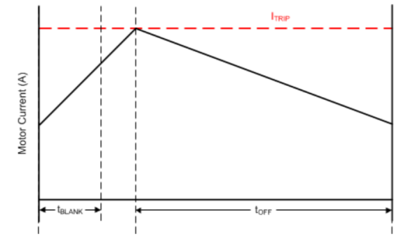
In stepper motors, the H-bridge goes into decay mode for Toff once the winding current goes above the set I_trip value (as shown in Figure 1 below). This regulation process defines the sinusoidal winding current waveform. Read the app note http://www.ti.com/lit/an/sloa170/sloa170.pdf for more details.


