This thread has been locked.

If you have a related question, please click the "Ask a related question" button in the top right corner. The newly created question will be automatically linked to this question.

DRV8353: The brushless motor is not working properly

Part Number: DRV8353
Other Parts Discussed in Thread: TIDA-00774

Hi Team,

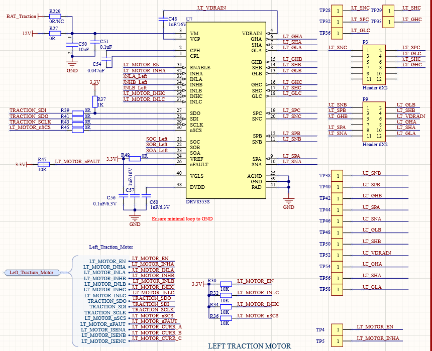
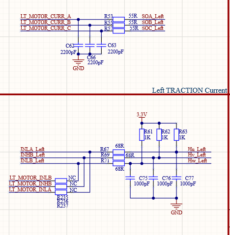
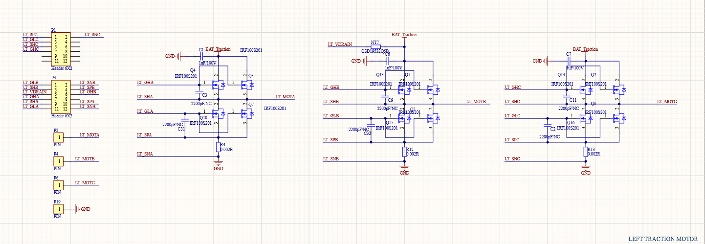
Customer uses DRV8353S to drive three-phase brushless motors with Hall.

1. At present, 2 chips have been burned, both of them are short-circuited in the lower bridge of the chip, and GLx and SPx are short-circuit. 147K at normal, about 5 ohms after short circuit. The chip is hot and the current is large.

2. The brushless motor can rotate, but the current is very large at low speed, about 1A. Brushless motor is small at high speed, about 0.5A. When the speed is low, the current of about 1A is obtained when the three phases of the motor are removed.

Customer would like to know how to resolve this issue?

Thanks,

Annie

  • Hello Annie,

    Can we see the customer schematic (DRV83353S & MOSFETs) as well as the device SPI settings?

    The most common issue we see is customers setting IDRIVE way too high - [FAQ] Selecting the Best IDRIVE setting and Why this is Essential

    Another possibility is voltage spikes on GLx and SPx due to layout. Please measure with an oscilloscope to see if at any point these pins violate the abs max ratings of the device.

    Thanks,

    Matt

  • Hi Matt,

    Pull-up drive current 300mA, pull-down drive current 300mA(Software setting). 

    Thanks,

    Annie

  • Hello Annie,

    I can see that the customer is implementing parallel MOSFETs, however they have not added resistors between the MOSFET gates. When you have parallel MSOFETs the input capacitance to the gates are never perfectly matched, and we have seen that this causes a significant amount of ringing when turning ON the MOSFET.

    TIDA-00774 gives an example of how this is done - we recommend between 3.3 and 10 ohms in series with each gate to dampen the oscillation of miss-matched capacitance.

    We also recommend adding bypass capacitors from the high-side drain to the low-side source. This can help mitigate any ringing on the low-side MOSFET source or sense resistor. Normally these capacitors should be in the range of 0.1 to 1 uF. Snubbers across each MOSFET can be implemented if you are observing significant ringing on the phase (SHx) - see this technical article for snubber design if this is relevant: LINK

    Thanks,

    Matt