This thread has been locked.

If you have a related question, please click the "Ask a related question" button in the top right corner. The newly created question will be automatically linked to this question.

DRV8884: Current accuracy

Part Number: DRV8884
Other Parts Discussed in Thread: DRV8886,

Hi team,

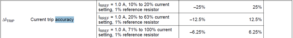
 When using the current setting by connecting a resistor between the RREF pin and GND, does the IFS accuracy change from ±6.25% when the IFS setting (resistor value) is changed?
 If the accuracy changes, can you tell me the relationship between the size of the IFS and the accuracy?

Regards,

Yamaguchi

  • Yamaguchi-san,

    The spec table lists different accuracy with different full scale current setting.

    Regards,

    Wang

  • Hi Wang-san,

    Thank you for the answer. I received additional questions from my customer. Could you please support the questions below?

    1. Is there any effect on the current accuracy when switching the TRQ signal? For example, when the IFS setting is 1A and TRQ=1 (50%), and when the IFS setting is 500mA and TRQ=0 (100%), the current is 500mA for both, but is the accuracy the same?

    2. When the IFS setting is 300mA, the IFS accuracy will be +/-12.5% from the spec table, and when the electric angle is changed and the phase current is 150mA, is another +/-25% added to the +/-12.5%?

    3. The customer would like to know the current accuracy in the following range. Is it possible to estimate it? (The recommended full-scale current for the DRV8884 is 1A, but the customer has checked the heat dissipation and confirmed that it can flow up to 1170mA. DRV8886 has been confirmed as well.)

     DRV8884 : 100mA to 1170mA
     DRV8886 : 900mA to 2720mA

    Regards,

    Yamaguchi

  • Yamaguchi-san,

    1. If the actual output current settings are same, the accuracy should be same. So, the accuracy should be same between 1A IFS with 50% TRQ or 500mA IFS with 100% TRQ.

    2. After the output current is changed from 300mA to 150mA, the output current accuracy could be changed from 12.5% to 25%, even the actual error is same. For example: 12.5% of 300mA is 37.5mA. The 37.5mA is 25% of 150mA. So, it is not another 25% added to the 12.5%. 

    3. The datasheet provides 10%, 20% and 71% accuracy data points. Other output current accuracy can be estimated by a linear interpolation (https://www.johndcook.com/interpolator.html) method. But, I don't think the estimation is needed if the current is higher than full scale current because customers cannot set the output current higher than the full scale current. 

    Regards,

    Wang Li

  • Hi Wang-san,

    Thank you for the answer.

    For the #3, is the following image correct?

    DRV8886 IFS accuracy.pptx

    Regards,

    Yamaguchi

  • Yamaguchi-san,

    Yes. That is the linear interpolation method. I want to use it to estimate the output current accuracy.

    Regards,

    Wang

  • Hi Wang-san,

    Thank you for the confirmation. I received additional questions from the customer. Could you please support the questions?

    (1). When I use a specific IFS as in Equation 1 in d/s, do I only need to consider the error in the graph that I sent you last time?
     (Does the error of the graph already include "ARREF variation", "RREF±1%", and "variation of absolute value of current", and do I need to consider the other three?

    (2). When using it as shown in Figure 16, in addition to the error in (1) above, is it necessary to consider the entire range of "VRREF variation" from 1.18 to 1.28V?

    (3). Considering the error of the current absolute value this time, it is beyond the acceptable range on our product.
     I would like to confirm that there is no problem from the ability variation of ARREF and VRREF.
     Could you please provide the distribution data of ARREF and VRREF variability?

    Regards,

    Yamaguchi

  • Yamaguchi-san,

    1) The datasheet ΔItrip accuracy spec is the DRV8884 internal parameter. It should cover ARREF. If RREF±1% is the external resistor's accuracy, it should not be included to ΔItrip accuracy because we don't know what resistor the customer uses.

    2)  When using it as shown in Figure 16, in addition to the error in (1) above, I think the entire range of "VRREF variation" from 1.18 to 1.28V should be considered.

    3) The distribution data of ARREF and VRREF need NDA agreement. Please send me an email to discuss it.

    Regards,

    Wang

  • Hi Wang-san,

    Thank you for your support. Could you please advise to my question below?

    For the question (2), I believe that the VRREF variation is already included in the equation (1) as ARREF. Is it correct?

    Regards,

    Yamaguchi

  • Yamaguchi-san,

    Yes, I think the VRREF variation is already included in the equation (1) as ARREF.

    Regards,

    Wang

  • Hi Wang-san,

    I received additinal questions about the question (1) . Sorry to the many questions.

    Additional questions

    a) Could you tell me more about the reason why the error of the absolute current value occurs?
     It would be better if you could explain it using a circuit block diagram, etc., as long as you can provide one, to make it easier to understand.

    (T.Y) I have told the cutomer following comment by Alvin-san's advice before. So I think that the customer would like to know more about this comment.

    The current trip ccuracy on p.7 of the datasheet was specified through simulation and test evaluation, considering that in practice there will be variations in the output Power MOSFETs and the accuracy of the built-in comparator.

    b) Does the error in the absolute value of the current included in (1) occur on both the + side and the - side?
     If not, I would like you to review the error in (1) to the correct value. For example, if the error is caused by an offset on one of the terminals of the comparator, it is sufficient to consider only the error on the + side or the - side.

    When we checked multiple ICs, when the IFS setting value was 1A, the pulse signal was input as shown in Figure16 in the d/s and the setting was 0.2A, it tended to be slightly higher than 0.2A (20 to 30mA). 
    (So far, no error has occurred on the minus side)

    Regards,

    Yamaguchi

  • Yamaguchi-san,

    a. To understand the current regulation error, the customer can read https://www.maximintegrated.com/en/design/technical-documents/tutorials/5/5693.html 

    b. A normal sample's error value should be in the range from  the + side and the - side. After DRV8884 detects the current reaches the regulation point, there is a 0.5us~1us delay from the current regulation point detection point to FET actually turn-off point. If the motor coil inductance is small, the output current can go up a little bit from the current regulation point detection point to FET actually turn-off point. So, on your test sample, the actually turn-off current point could be slighter higher than the regulation point.

    Regards,

    Wang