Hello team,
I'm posting this inquiry on behalf of my customer, please see details below.
Using your development tool I’ve made power supply system (power net.pdf), with little adjustments (for supply_1 vout changed and added 6th phase) applied it in design. Resulting design for supply_1 is in P9_RB.pdf.
I’ve got several questions about TPS53667 operation:
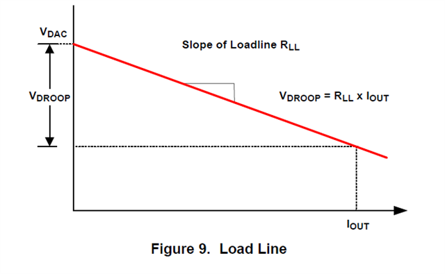
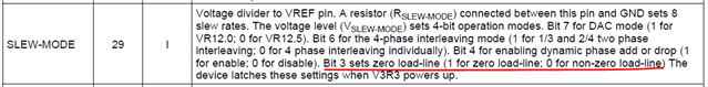
- How load line setting is working? I changed this parameter from 1 mOhm to 0 and to 2 mOhm, applied and released 30A load, but Fluke multimeter’s readings under load (not near power supply, but exactly where load is situated) did not change. Why or what I don’t understand? What should I expect when I change this value?
- Using https://www.ti.com/lit/ug/slvu719b/slvu719b.pdf?ts=1638444709036&ref_url=https%253A%252F%252Fwww.ti.com%252Fproduct%252FTPS53819A and figure 4-1 technique I’ve made oscillograms when I applied 30A load (LeCroy.png) and released load (LeCroy1.png). According oscilloscope more load results in more Vout (constant level is up to 70mV higher), but Fluke shows what it don’t happen. What do I do wrong?
Regards,
Renan