This thread has been locked.

If you have a related question, please click the "Ask a related question" button in the top right corner. The newly created question will be automatically linked to this question.

BQ27441-G1: No communication over I2C

Part Number: BQ27441-G1
Other Parts Discussed in Thread: BQ51050B

Hi TI team,

we have some strange problems with the battery fuel gauge.

With no change in our code we cannot communicate with the gauge over I2C.

The Vdd of the gauge is at 1.8V.

I2C SCL and SDA lines are HIGH (but we also had a case where SCL or SDA were permanently low and Vdd at 0V).

Things we already tried, but didn't work:
- Resetting the comm engine by pulling down I2C SDA/SCL for 2s (even tried 3s and 4s) https://e2e.ti.com/support/power-management-group/power-management/f/power-management-forum/967941/bq27542-g1-fuel-gauge-holding-the-scl-line-to-low-and-i2c-bus-locked---working-only-by-doing-a-power-reset-that-is-not-possible-in-our-device

- Pulling GPOUT low for 1ms to try to wakeup gauge.

- Sending Reset and SoftReset commands over I2C

We were able to reproduce this state by performing the following steps:

- The attached battery is empty

- Attached our device to an QI charger (charger chip on our device: BQ51050B)

- Now the gauge won't respond to any i2c communication

The only way we can get the gauge to work again is by reattaching the battery as the gauge is powered over the battery, which is not a suitable workaround for us, because we have thousands of devices in field.

Thank you for your support in advance!

Thanks,

Clemens

  • Does the gauge respond after you attach the battery and before you connect the QI charger?

    How reliably can you reproduce this?

    Is this always related to attaching the battery?

    What's the voltage of the battery (you mentioned empty - but what does that mean w.r.t. battery voltage)?

    Is there a chance that the gauge temporarily loses power during this process? If, by any reason, the capacitor on VDD is charged before you power up the gauge and if the capacitor is back-powering the gauge in this scenario, then the gauge may not start up reliably.

  • Sorry the steps for reproducing the issue were misleading, I just edited them. The battery is still attached but empty. After connecting the QI charger it charges, our devices starts to work, but the gauge doesn't.

    I was able to reproduce it reliable. The battery really needs to be discharged and then it should relax some hours, before attaching the charger.

    It is always related to attaching a qi charger, when the battery is empty.

    The multimeter reads 0V

    I will have a look at the temporarely power loss.

  • Things I also tried:
    - Pulling SCL low for 2000ms

    - Pulling SDA low for 2000ms

    - Trying to write to 0x16 (0x0F to I2C register 0x00 and 0x0F 0x00 to I2C registers 0x64 and 0x65), but resulted in NACK.

  • Voltage at battery during attachment of charger seems stable. 

  • I can't make the picture larger (TI's internal network blocks the image hosting service).

    Please clarify: When the battery is empty, the battery voltage is 0V (I assume because a protector opens protection FETs). An empty rechargeable cell still has a voltage high enough usually to power the gauge so this looks like there was an under voltage protection event, correct?

    When you attach the QI charger, how does that affect the voltage on pin 6, BAT and what's the voltage on pin 5, VDD when the QI charger is attached? Do you have screen shots? The forum will let you insert pictures directly. Click on Insert and click on the upload line, then browse to the image on your PC. For example:

  • Yes, battery was in undervoltage protection.

    I don't have screenshots, but I will try to reproduce the issue and capture them.

  • Can you please try the following for a gauge that doesn't respond:

    Check if you can read one byte from I2C device address 0x16 (8-bit extended or 0x0B 7-bit), not 0xAA (8-bit extended or 0x55 7-bit)?

    The gauge will, under certain circumstances launch a different firmware when it is powered up, which responds on 0x16 instead of 0xAA. This is a TI-internal only diagnostics FW. If it responds on 0x16 then it's possible to send a command to launch the actual gauging FW, which could be a workable solution. Would it be possible to share the schematics?

  • The gauge doesn't respond to this address.

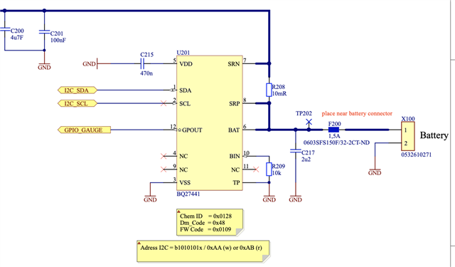
  • What's the state of GPIO_GAUGE when the charger is attached? does the host uC drive this low or high or is it high impedance during the 3s power on ramp? The gauge will use this pin in push-pull configuration during boot and this must not violate the VDD+0.3V limit (see table 8.1)

  • It should be HIGH. The uC output is configured as open drain and it is not driven low. The pin is pulled high to VDD of the system (3.3V) over a 10k.

    So should we use a software controlled pullup instead of a soldered pullup?

  • If you are able to reproduce the failure, then I recommend soldering a pull-down resistor (not a pull-up) to GPOUT. The gauge uses this pin as an output during boot up briefly, driving it high and low so if something else (e.g. the uC) drives it, then it will be a short circuit. If it's pulled to 3.3V then it's above VDD+0.3V (With VDD = 1.8V from the gauge LDO), so that won't work either. It must be pulled to ground with a resistor.

  • Ok, we will try this. In which application note or datasheet is this noted, that the gauge is driving GPOUT high and low during boot. I only found that it is configured as open-drain output.

  • Using a 10k pulldown on GPOUT we still were able to reproduce the failure.

  • Thanks for checking GPOUT. This rules out several potential causes.

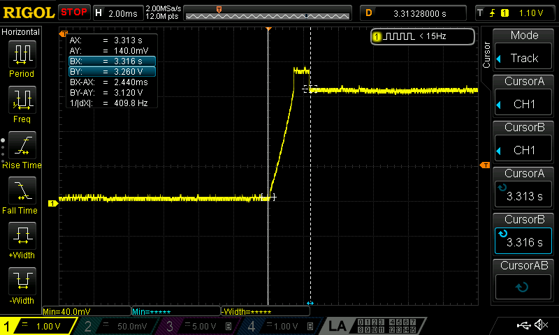
    I'd like to revisit the question that I asked earlier last month about the state of VDD: "and what's the voltage on pin 5, VDD when the QI charger is attached?"

    The gauge may not boot up, if the voltage on VDD wasn't zero when the gauge is powered up again. This is a very unusual situation because the gauge's internal circuit will discharge the capacitor on VDD if the gauge is powered down. However, if the loss of power is abrupt (e.g. the capacitor on BAT (C217 in your schematics) gets discharged within a few microseconds due to power draw from other circuits on the board), then the gauge won't turn on a low impedance path on VDD and the charge on the VDD capacitor (C215) can linger for a long time. If the voltage on VDD is not close to zero due to this capacitor, then this may cause issues starting back up. This is the only remaining mechanism of action that I can think of.

    Does the effect correlate with the time the battery was disconnected from the gauge due to a low voltage protection event? If this is a test scenario, where the charger is attached within a few seconds from a protection event, chances are that the capacitor on VDD is still charged too high. If this is a use case where the battery was disconnected for a long time (several minutes, hours...) then this is another root cause that I can't identify with the information that was provided.