This thread has been locked.

If you have a related question, please click the "Ask a related question" button in the top right corner. The newly created question will be automatically linked to this question.

Input source Power management

Other Parts Discussed in Thread: BQ24133, BQ25792, BQ24170, BQ24610, TPS25750, TPS65987, TPS65988, TPS65987D, HD3SS3412, TPS25750EVM

Hi,
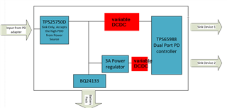
I have four main components. 1: Dock station for Tablets. 2: Wireless charger for Cell phone. 3: Custom PCB Board. 4: Battery. The dock station is connected with an external PD adapter. This input power is also shared with a custom PCB board. The custom PCB board will simply connect the input power with a wireless charger and dock station depending on which power source is active. If the PD adapter is active then custom PCB will transfer power from the dock station to the wireless charger and charge the battery. When input power is not available then a custom PCB board will connect the battery power with a wireless charger and dock station.

Now I need help in choosing the IC that can manage power sources i.e. if an input adapter is present then the battery will only charge and when the input adapter is not present then connect the battery pack with the rest of the system but as soon, input power came back to switch to the input supply again. The main idea is the same as UPS supply.


  • Hi Ali,

    Take a look at BQ24133. It has traditional power path, which is what I understand that you need.  

    Regards,

    Jeff

  • Hi,
    Thanks for your reply. Plz, check the attached file for a better understanding of what I am looking for. I think BQ24133 or a similar device can do the job but still, I am confused about many points.
    1: When I connect the PD adapter directly with a wireless charger. It enters into fast charging mode because it is PD enabled. Now I can't simply connect power rails with the wireless charger and expect it to charge in fast mode. Maybe I am wrong.
    2: I don't want to get power from a custom PCB when the adapter will present for the dock station. How I can bypass it? While dock station should get power from custom PCB when an adapter is not present. The Custom PCB is connected with the dock station through power rails only at one terminal.
    3: The dock station is capable to charge devices in fast mode when the PD adapter is present. How will get this feature when the battery will connect with the system?

    BLOC DIAGRAM.pdf

  • Hi Ali,

    I do not understand what you are trying to do with the wireless charger.  How does the 4.2V battery get charged?  When is the battery discharged, only to power the wireless charger?

    Regardless, we only have 2 types of battery chargers, those like the BQ24133 with traditional power path, and those with NVDC powerpath.  The NVDC powerpath devices, like BQ25792, provide a SYS rail = higher of user set minimum system voltage or final battery regulation voltage (e.g.4.2).  The BQ24133 is standalone, meaning configured with external resistors, while the BQ25792 requires a host processor to set I2C registers.

    Regards,

    Jeff   

  • Hi @Jeff
    Let me explain to you in more detail.
    I have a single cell lipo battery as a backup source. I have PD adapter as a primary input power source which will attach with Dock station.
    When adapter will be connected then power from dock station will share with custom PCB(Directly connect PD adapter rails with custom PCB). Now custom PCB will have some battery charging IC, step up/down converter which will charge the lipo battery and also share the PD adapter power with the wireless charger. If you are getting confuse with charger then assume there is a device which require 5V 3A input power.

    Now in the 2nd case, the adapter is not present. I have to get the whole system power from battery. The custom PCB will step up lipo battery voltage to provide it to both dock station and charger. As soon, the adapter power come back. The system will switch back to primary power source.
    Mainly, I  have two devices which consumes power i.e. Dock station and wireless charger.
    I hope it answered all your questions.

    As you know the PD adapter can provide power upto 30 to 60W. I need an IC similar to BQ24133 which can handle that much power during sharing in different cases.
    Thanks

  • Hi Ali,

    The BQ24170 family is the higher current (power) version of BQ24133.  If you need even more power, you can move to a charge controller with external power FETs like BQ24610.

    Regards,

    Jeff

  • Hi Jeff,
    Thanks for all your help. I hope I am not annoying you with my stupid questions. Actually, It is my first design with PD controllers and I am a bit confused. I created a rough sketch of how the whole system work to explain further.
    I have the following questions if you can answer them plz.

    1. I have two different input Sink devices connected with my PCB while single input power source i.e. Adapter or Battery. What I should add further in the system so it can distribute a single source supply to two different sink devices.
    2. Did I create the correct sketch? Most probably, I will translate it in the same way in my design.

    Thanks for all your reviews and suggestions

    .1680.SCH.pdf 

  • Dear Ali,

    I will get back to you by next Tuesday.

    Thanks,

    Mike Emanuel

  • Ok, I will wait for your feedback

  • Hi Ali,

    Mike and I support the chargers and are not USB protocol experts.  Mike and our USB-C team developed a reference design using the BQ25792 charger and TPS25750 port controller.  The BQ25792 is an NVDC charger that does not pass through the input power to the system but rather provides the higher of a minimum voltage or the battery voltage to the system.  In other words, the charger’s converter must pass both the system current and the charger current.  The ref design is at the link below.  
    https://www.ti.com/tool/USB-PD-CHG-EVM-01

    Please review this and then we can decide if we need to get the USB team involved.  

    Regards,

    Jeff

  • Hi Jeff
    I noticed that this IC is I2C based and I don't want to get involved in the programming part. Can i use it standalone or i have to set up the register settings of this IC? If yes, then i want to avoid it. Is there any other alternative to it?

  • The BQ25792 charger requires I2C but the TPS25750 firmware does most of the communication.

  • I studied the datasheet. I noticed the following points. Correct me if I am wrong

    1. Input support PD input feature. It can connect with a PD adapter to adjust input voltages according to the load 
    2. It can charge a lipo battery and provide an output when the input source will not present by converting battery voltages to PD compatible output
    3. It can provide output to only one sink device
    4. I searched about PD pinout for USB C and found that it required only CC pins along with the power to adjust the voltage and current of the system. I am not sure about it but read in an article TI posted.

      Thanks

  • Hi Ali,

    Regarding 1 and 4, the charger cannot communicate directly with USB type C ports because it has no CCx lines.  With the help of a USB IC and/or host processor, the charger can provide the PD voltage steps up to 20V when it is operating in reverse/OTG mode.

    Regarding 2, yes in reverse/OTG with that output being at VBUS pin.

    Regarding 3, yes. 

    Regards,

    Jeff

  • Can we ask some USB Expert to help me to figure out this solution?
    I have to provide power to two sink devices. I need communication with the input PD adapter to adjust voltages according to sink demand. I need to convert battery voltage to PD output voltages for both devices same as the input PD adapter.

  • Ali,

    There are 2 ports that can meet your needs:

    1.  The TPS25750.  This part will work as long as the selected charger that you are using is able to manage the output current limit for outputs greater than 5V.  This is the simplest and lowest cost solution.

    2.  If your charger cannot manage the output current limit to meet the type C specs, then you will need to select the TPS65987DDH will meet your needs.

    Regards,

    Chuck

  • Hi
    The TPS65987 is out of stock. That's the reason, I skipped designing my own dock station and bought OTS. Now I am again at the same stage.
    Can you suggest to me some other alternatives?
    Thanks

  • Ali,

    I do not have any other part options that would fit your needs.  We are doing the best we can to address stocking issues.  We update the stocking on a daily basis, so the best suggestion that I can offer is to keep trying to see if you can find parts in stock.

    Regards,

    Chuck

  • Hi
    I found stock. I started to design. I will keep you in the loop during design. Maybe i need some guidelines about starting points

  • Hi
    I created the block diagram. I believe that I am on the right track now. Can you review it plz>?
    I don't need any TBT or Display port feature. I just have to bypass the input power supply to the two different sink devices.
    Thanks
    6445.BLOCK DIAGRAM.pdf

  • Ali,

    I am going to transifer this over to our Marketing engineer so that he can help you with part selection.

  • Hello,

    Looking at your block diagram, will there be two Type-C ports for the sink devices? Why I ask is that the TPS65987D is a single port PD controller so if you are wanting to implement two Type-C PD ports, your best bet would be to use the TPS65988 which is a dual port PD controller


  • Thanks for your reply.
    Yes, there are two USB C ports with different ratings i.e. 15W PD Enabled and 60W PD Enabled. I will use TPS65988 in that case.
    I was thinking those are two ports lines PP_HVX. I am also a bit confused that how the input adapter wiring should connect with the input of the PD controller while charging the circuit in the loop.
    How the power will negotiate between PD control and PD input Adapter? Or i just provide 5V VBus to PD controller and it negotiates with the sink devices on its own?
    Thanks

  • Hello,

    You can refer to the TPS65988EVM as reference for how to connect the power paths. For the PD negotiation, the TPS65988 will handle this on its own. You will use the GUI to create a unique configuration, and load this image to our controller using an external EEPROM. If you go to the TPS65988EVM page and scroll to the getting started section, you will see our GUI training video series. 

  • Hi
    As I don't need a Display port or USB A port. So I should skip (HD3SS3412 and TUSB8020) parts in the EVM reference design. I only need to provide power paths to sink devices connected to my board.
    Thanks

  • Yes, since you do not need either of those features and only care about the power, you can ignore those devices.

    Also, for the other bottom Type-C port connected to the battery charger, you will also need to have a PD controller here as well. You can look at the TPS25750, specifically the following reference design which can be paired with a battery charger directly. 

    www.ti.com/.../USB-PD-CHG-EVM-01

  • Yes, I was discussing it with . He mentioned me system like that to make it work.
     .
    I checked the TPS65988 EVM schematic and user guide and I noticed that EVM used a DC barrel jack and different converter for different voltages levels i.e 5V, 9V,20V, etc. I am also open to using it instead of a PD adapter. Is that the option, I can use in my application instead of a USB C-based adapter?

  • Yes that block diagram would work. You would still need some sort of DCDC to provide the needed power to the donwstream type c device. So referring to the TPS65988EVM, instead of the barrel jack providing the 20V to the DCDC, you would have the Type-C port controlled by the TPS25750 provide the 20V

  • Hi
    Can you provide me with the part number for TPS65988? I am following EVM as a reference design but I couldn't find the part number mentioned in the BOM list.
    Thanks

  • Also, if you can help me to understand the difference between these three-part numbers.

  • Hi Ali,

    You will use the TPS65988DHRSHR. Let me know if you have any additional questions. 

  • Hi
    Thanks for the part number information. Is it possible if you can provide me PCB design files for EVM or at least schematic pdf only? The EVM guideline schematic isn't very good in resolution. Most TI EVM board design files are available but  I could not find this one.
    Thanks

  • Hello, 

    Attached is the schematic.

    ACS009B(001)_Sch.PDF

  • Hi 
    I have a quick question regarding input power negotiating.
    I the EVM, we have a Variable power supply after the DC jack. I believe that by controlling MOSFET switching, the desired input voltage is selected by TPS65988 for output ports.
    Now my question is about the PD input adapter. If I will use the PD adapter then definitely, I don't need variable supplies because the PD adapter can provide negotiated voltage on its own.
    How this communication will take place?
    In EVM, there is no such communication but TPS65988 setup voltages on its own at input according to the output requirements. Am I correct?

  • Hello,

    No you will still need some type of variable DCDC in between, especially if you are wanting to offer more than 5V for your downstream sink devices. 

    The TPS25750 will basically be used as a barrel jack replacement device. The EVM is powered by barrel jack that provides power to the DCDCs. For your system, instead of a barrel jack providing this power, you will have a Type-C port controlled by the TPS25750

  • Thanks for your reply.
    Much appreciated

  • Hi 
    I am moved back to DC adapter design to make things simple. Can you help me to select the DC power jack attached to the EVM Board? I couldn't find it on main distributor website and I also don't know what particular parameters are considered while choosing this jack except current 10A and Voltage rating <=50V.
    Is there any other parameter that I should consider?
    What is the function of the Sense pin in that connector?
    PD1135-509-7F

  • Hi Ali,

    Personally I would not recommend using this connector type on your system. You highlighted the main limitation which is the fact that it is incredibly difficult to source. Our team has a large storage of these which is why we continue to use it. 

    Using the TPS25750 on the sink only port would not add that much complexity to your design. From a procurement perspective, it will likely be easier since Type-C connectors will be much easier to source than this barrel jack. 

  • Thanks for the reply.
    With that said, I have to take input from a USB C adapter and pass it to the TPS25750. Then the output of TPS25750 to the TPS65988.
     In this way, I have to use it in the following ways.


    1. TPS25750 is always in sink mode. It will receive input power through a USB C port

    Can you send me a schematic of TPS25750 with BOM for its EVM? I found two EVM boards. It seems to me that both have the same circuit with a little difference in battery charging IC or TIVA circuit configuration with one of them.


  • Should I follow this EVM reference design as a start?
    https://www.ti.com/tool/TIDA-050047
    I can also see all required files on this link.

  • Hello,

    TPS25750 is always in sink mode. It will receive input power through a USB C port

    Yes this is how the TPS25750 will be used for your system. 

    I found two EVM boards. It seems to me that both have the same circuit with a little difference in battery charging IC or TIVA circuit configuration with one of them.

    You can use either the EVM or the reference design you highlighted. All you will focus on is the setup of the TPS25750 itself and its connection to the Type-C connector. You will configure the device to act as a sink only using the GUI and then pass the VBUS voltage to your system using the PPHV pin. 

  • Hi 
    I studied further and got almost everything but I still have some doubts regarding communication between TPS65988. Here is my understanding so far.

    1. The TPS25750 will negotiate power for a battery charger(BQ25792) with an adapter and set up charging voltage and current based on the profile saved in EEPROM using GUI.
    2. The TPS65988 will set up sink ports voltages and current by negotiating with the input source connected.
    • Now my question is how TPS65988 will negotiate the desired sink profile with the input source?. As in my case, it will be the system output from BQ25792.
      Also, What are the Aardvark connector and internal debug connector on BQ_EVM?
    • What will be the system output range from BQ25792?
    • Can I set up BQ25792 for the 1S battery because it is mentioned that EVM is for 2s to 4S?

    See the attached figure.
    Thanks
    BLOCK.pdf

  • Hello Ali,

    You block diagram is not correct. For the TPS65988, you will need to have a dedicated DCDC for each of the Type-c ports similar to what was done on the TPS65988EVM. You cannot have the BQ25792 feed the voltage for both of the TPS65988 Type-C ports. 

    You block diagram would be something like the below

  • Yes,
    This makes more sense now.
    Thanks for your reply.
    I am about to complete the schematic till BQ25792. As soon, I will complete the schematic. I  will send you for a review. Thanks for all your assistance sir.
    Really appreciate it.

  • Hi Ali,

    Glad I was able to help. Feel free to share the schematic whenever it is ready for review 

  • Hi
    Can you send me the updated BOM of TPS65988EVM plz?
    The BOM given in the User guide does not match many components. For example, U9 given at BOM is TPS62097RWKR while used TLV62568DRLR in the schematic. There are also some different designators than actual schematic which is bit confusing.
    Thanks

  • Hello Ali,

    Attached is the BOM. Let me know if you have any additional questions. 

    ACS009B(001)_BOM.xls

  • Hi
    I attached the schematic of the board. It is actually the combination of two EVM boards i.e. tps68988 and tps25750. I didn't connect the output of tps25750 with tps65988 because I have some questions. But can you review it Plz?
    POWER DISTRIBUTION BOARD.pdf

  • Ali,

    Our US team and India team will be out of the office on Holiday until Monday April 18th.

    You will receive a response on Monday


  • Any update sir about the review of Schematic. I am also worried about the cost of components of TI. I just received a quotation from my PCB supplier which is insanely high.
    I also need help getting the quotation of all the components of TI for this project.
    I can share the BOM of the project. 
    Also, if any components are not in stock then how we can replace them with some other. It will be a huge disaster for me if I have to change the main ICs or wait till 2024 to get it.
    My first batch order target quantities are 500pcs to 2000pcs. I am open to any suggestions regarding this.
    Thanks a lot for all your help.